目录
电气导管在保护电线免受损坏、确保电气系统安全可靠运行方面起着至关重要的作用。无论是在住宅、商业还是工业应用中,电气导管都能保护电线免受物理伤害、潮湿、火灾和其他环境危害。管理电气导管使用和安装的最重要标准之一 澳大利亚和新西兰的电气导管 是 AS/NZS 2053。该标准提供了有关各种导管系统的类型、材料和安装实践的详细指南,确保它们满足必要的安全和性能标准。
在此综合指南中,我们将深入探讨三个主要的 AS/NZS 2053 标准:
AS/NZS 2053.2–电气设备用导管和配件–绝缘材料制成的刚性普通导管。
AS/NZS 2053.6–电气设备用导管和配件– 绝缘材料制成的异型壁光滑内孔导管和配件。
AS/NZS2053.5 – 电气设备用导管和配件第 5 部分绝缘材料波纹导管和配件
我们将详细分析其范围、主要规定以及它如何适用于不同类型的电气导管,包括硬质 PVC 导管、柔性 PVC 导管和波纹导管。了解这项标准对于在这些地区设计、安装或维护电气系统的电工、承包商和工程师来说至关重要。
通过阅读本文,您将获得以下方面的宝贵见解:
- AS/NZS 2053 标准的范围及其与各种类型的导管系统的相关性。
- 该标准涵盖的不同类型的电气导管,例如硬质 PVC 导管、PVC 导管、柔性 PVC 导管和波纹导管。
- 导管材料必须经过的测试程序,以满足所需的安全和性能标准。
- AS/NZS 2053 在不同电气装置和环境中的应用。
- 遵守 AS/NZS 2053 规范对于确保电气系统安全耐用的重要性。
注:本文所有内容均基于 AS/NZS 2053 2001 版本,并 归澳大利亚标准局所有.
了解澳大利亚标准
澳大利亚标准协会在电气管道法规中的作用
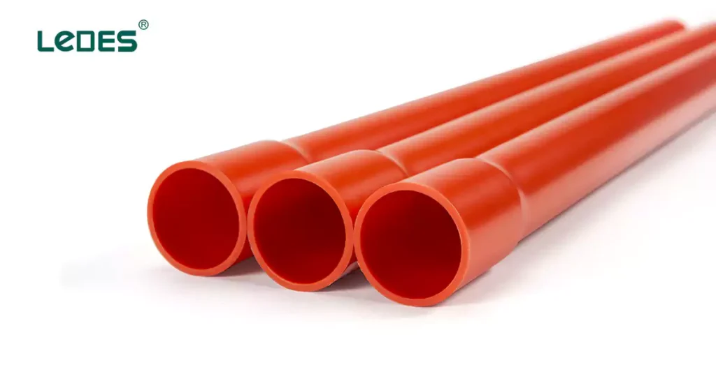
澳大利亚标准协会是澳大利亚全国性标准组织,负责制定和发布澳大利亚各行各业的标准。该组织在确保产品和服务(包括电气系统)的安全、质量和性能方面发挥着重要作用。通过制定和更新行业标准,澳大利亚标准协会确保电气设备达到最高安全性和可靠性水平,从而降低电气危险风险。
AS/NZS 2053 标准是澳大利亚标准协会和新西兰标准协会共同努力的成果。它是一套更广泛的指导方针的一部分,旨在确保两国电气系统安装的统一性和一致性。AS/NZS 2053 不仅对澳大利亚电工和工程师至关重要,而且也是新西兰电气安装的重要参考。该标准适用于各种类型的电气导管,为其构造、安装和测试提供指导,以确保它们符合安全和性能要求。
AS/NZS 2053 等电气标准的制定符合国际最佳实践,同时也满足了澳大利亚和新西兰市场的独特需求和条件。遵守这些标准对于遵守国家建筑规范和法规至关重要,从而确保电气系统和与之合作的人员的安全。
AS/NZS 2053 的范围
AS/NZS 2053 标准为电气导管系统(包括金属和非金属导管和配件)提供了全面的指导方针,确保它们满足安全性、耐用性和性能要求。该标准的范围涵盖导管系统的各个方面,包括材料、安装实践和测试程序。其主要目标是保护电线免受外部因素的影响,例如物理损坏、潮湿、火灾和化学暴露。
AS/NZS 2053 中定义的导管类型
1. AS/NZS 2053.2 – 绝缘材料刚性平面导管
本节重点介绍用于为固定安装中的电线提供强大保护的刚性普通导管。
涵盖的导管类型:
PVC 硬管: 由于其重量轻、耐腐蚀、阻燃和易于安装,因此被广泛使用。这些导管适用于外露、嵌入式或地下布线系统。
非火焰传播导管: 专门设计的导管可在发生火灾时最大程度地减少火焰蔓延,从而提高安装的整体安全性。
应用:
住宅和商业建筑中的墙壁和天花板安装。
基础设施项目中的地下电缆保护。
暴露的设施需要抗紫外线和防风雨的解决方案。
2. AS/NZS 2053.5 – 绝缘材料波纹管和配件
该标准的这一部分定义了全波纹导管,这种导管重量轻、灵活性高,是需要适应性的动态安装的理想选择。
涵盖的导管类型:
PVC波纹管: 由于其适应性,这些导管被广泛使用,非常适合在狭小空间或频繁移动的区域安装。
紫外线稳定波纹管: 这些导管专为户外使用而设计,可抵抗紫外线辐射和极端天气条件。
应用:
在狭窄或密闭空间内进行电线安装。
频繁运动的动态系统,例如机器人或机械。
需要抵抗环境压力的户外设施。
3. AS/NZS 2053.6 – 绝缘材料异型壁光滑内孔导管和配件
这种导管具有波纹外壁,具有柔韧性和强度,内孔光滑,便于拉动电缆。这些导管非常适合需要兼具适应性和耐用性的安装。
涵盖的导管类型包括:
型壁 PVC 导管: 其外观呈波纹状,可增强灵活性和强度,内表面光滑,可轻松拉动电缆。
应用:
公用事业网络中的地下电缆布线。
灵活的安装需要光滑的内壁以最大限度地减少电缆摩擦。
化学腐蚀环境中的基础设施项目。
AS/NZS 2053 涵盖的关键领域:
AS/NZS 2053 主要与以下国家相关:
澳大利亚: 该标准在全国范围内得到广泛认可和采用,成为许多地方电气法规和合规要求的基础。
新西兰: 该标准在新西兰也得到认可,使两国的做法保持一致,并确保电气装置符合类似的安全和性能标准。
AS/NZS 2053 的主要内容
AS/NZS 2053 系列是澳大利亚和新西兰电气导管标准的基石,为电气安装导管和配件的设计、构造和性能提供全面的指导。这些标准确保了各种应用的安全性、可靠性和兼容性。在本节中,我们将总结前面介绍的三个关键标准涵盖的主要方面:AS/NZS 2053.2、AS/NZS 2053.6 和 AS/NZS 2053.5。
1. AS/NZS 2053.2 – 绝缘材料刚性平面导管
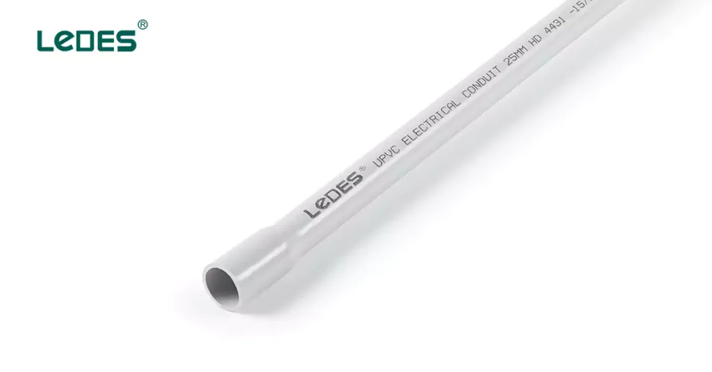
本标准提供了电气设备中使用的刚性普通导管的详细规格。它概述了:
材料要求: PVC 等绝缘材料的标准,确保耐用性、电气安全性和抵抗环境因素的能力。
方面: 刚性导管直径和长度的规格。
机械性能: 强度、抗压和抗冲击性的规格可满足不同的工作分类。
性能测试: 评估耐火性、电气绝缘性和紫外线稳定性的标准。
2. AS/NZS 2053.5 – 绝缘材料波纹管和配件
本系列的这一部分讨论了波纹管的独特特性,重点强调:
设计规范: 罗纹结构增强了灵活性并减轻了结构重量。
方面: 刚性导管直径和长度的规格。
材料要求: PVC 等绝缘材料,具有高灵活性和耐用性。
机械性能: 抵抗冲击、压缩和动态运动的标准。
3. AS/NZS 2053.6 – 异型壁光滑内孔导管和配件
本标准主要针对外部壁呈异形且内孔光滑的导管。它包括:
材质标准: 适用于柔性、轻型导管的绝缘材料。
尺寸要求: 壁面轮廓和钻孔光滑度的规格,以方便拉动电缆。
机械和热性能: 柔韧性、抗冲击性和热稳定性的标准。
AS/NZS 2053 详细介绍
AS/NZS 2053.2 – 刚性普通导管和配件
AS/NZS 2053.2 是 AS/NZS 2053 系列中的重要标准,规定了由绝缘材料制成的刚性普通非螺纹导管和配件的要求。这些导管主要用于保护电气设备中的电缆,确保机械保护和电气安全。本节详细介绍了该标准、其分类、尺寸、机械性能以及相关的测试程序。
范围和总体概述
AS/NZS 2053.2 适用于:
刚性平面导管: 不可螺纹,由 PVC 等绝缘材料制成。
配件: 诸如接头、弯头和适配器等配件专为与这些导管一起使用而设计。
分类
分类依据 机械性能:
- Vert 轻型刚性导管
- 轻型刚性导管
- 中型刚性导管
- 重型刚性导管
- 超重型刚性导管
分类依据 电气特性:
- 具有电绝缘特性
尺寸要求
该标准定义了精确的尺寸要求,以确保安装过程中的兼容性和统一性。
圆形导管尺寸(尺寸表)
公称尺寸 | 外径 | 壁厚 | ||||||||
平均直径 | 非常轻便 | 轻型 | 中型 | 重负 | ||||||
最小。 | 最大限度。 | 最小。 | 最大限度。 | 最小。 | 最大限度。 | 最小。 | 最大限度。 | 最小。 | 最大限度。 | |
16 | 15.7 | 16.0 | / | / | / | / | 1.6 | 1.9 | / | / |
20 | 19.7 | 20.0 | / | / | / | / | 1.8 | 2.1 | 2.3 | 2.6 |
25 | 24.7 | 25.0 | / | / | / | / | 1.8 | 2.1 | 2.5 | 2.8 |
32 | 31.7 | 32.0 | / | / | / | / | 2.1 | 2.4 | 2.7 | 3.0 |
40 | 39.7 | 40.0 | / | / | / | / | 2.4 | 2.7 | 3.1 | 3.4 |
50 | 49.7 | 50.0 | / | / | / | / | 2.8 | 3.1 | 3.4 | 3.9 |
63 | 62.7 | 63.0 | / | / | / | / | 3.0 | 3.5 | 3.9 | 4.5 |
65 | 75.2 | 75.5 | / | / | / | / | 3.0 | 3.5 | 3.9 | 4.5 |
80(新西兰) | 82.3 | 82.7 | / | / | 2.2 | 2.6 | 3.2 | 3.7 | 4.2 | 4.9 |
80(澳大利亚) | 88.7 | 89.1 | 1.8 | 2.2 | 2.4 | 2.8 | 3.5 | 4.1 | 4.6 | 5.3 |
100(新西兰) | 110.0 | 110.4 | 2.2 | 2.6 | 2.9 | 3.4 | 4.3 | 5.0 | 5.7 | 6.5 |
100(澳大利亚) | 114.1 | 114.5 | 2.3 | 2.7 | 3.0 | 3.5 | 4.5 | 5.2 | 5.9 | 6.7 |
125 | 140.0 | 140.4 | 2.8 | 3.3 | 3.7 | 4.3 | 5.5 | 6.3 | 7.2 | 8.1 |
150 | 160.0 | 159.5 | 3.2 | 3.7 | 4.2 | 4.8 | 6.3 | 7.1 | 8.3 | 9.3 |
导管长度表
导管尺寸 | 长度 |
最大至 63 码 | 4 米 + 20, -0 毫米 |
63 码以上 | 6 米 + 50, -0 毫米 |
机械性能
该标准概述了严格的机械性能要求,以确保导管和配件能够承受各种压力:
弯曲强度:
AS/NZS 2053.2 中描述的弯曲测试评估了导管在安装或使用过程中承受弯曲力的机械柔韧性和耐用性。该测试可确保按特定机械应力水平分类的导管能够承受弯曲而不会出现明显损坏,从而保持其功能性和完整性。以下是标准中概述的要求和程序的摘要:
Applicability
The bending test applies only to certain classifications and sizes of conduits:
Applicable Conduits:
Conduits with diameters less than 32 mm.
Those classified as suitable for:
Very light mechanical stress.
Light mechanical stress.
Medium mechanical stress.
Exempted Conduits:
Conduits with diameters equal to or greater than 32 mm.
Heavy-duty and very heavy-duty conduits, which are not required to undergo this test.
Test Procedure
The bending test involves the following steps:
- Placement:
Position the 500 mm test piece in the groove of the bending device, securing it lightly with the clamp.
- Bending:
Use the bending rollers to move the test piece around the former, creating a bend of approximately 180°.
After release, the test piece should retain a bend of 90°.
- Removal:
Remove the bending device without causing additional damage to the test piece.
Acceptance Criteria
After completing the test:
- The conduit must exhibit no cracks visible to normal or corrected vision without magnification.
- The conduit’s structural integrity must remain intact to ensure suitability for electrical installations.
Compression Resistance:
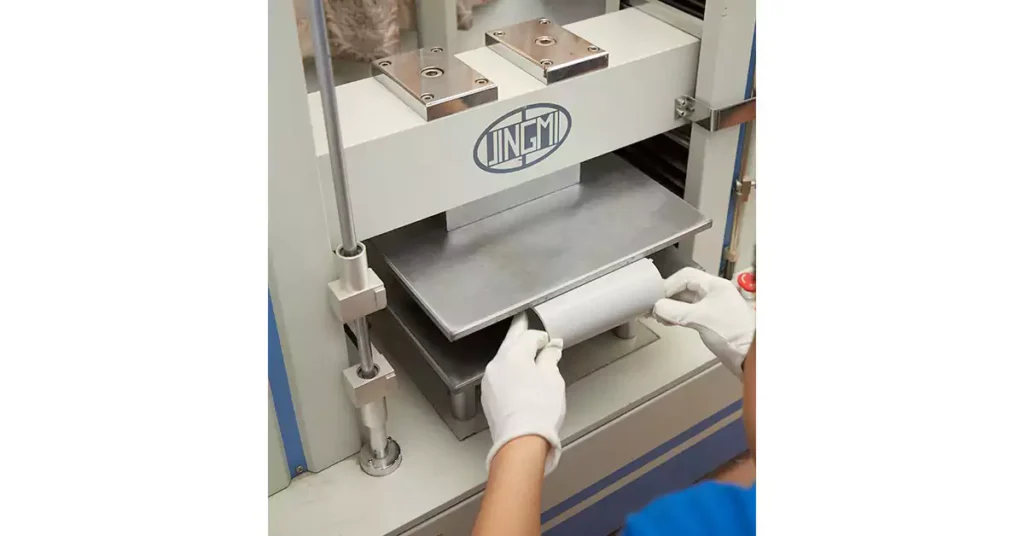
The compression resistance test ensures that conduits can withstand compressive forces during installation and operational use without significant deformation or compromising structural integrity. This test evaluates how well a conduit maintains its shape and performance when subjected to specified loads.
Applicability
The test applies to all conduits covered under AS/NZS 2053.2 and references the general compression resistance test outlined in Part 1 of the AS/NZS 2053. For a conduit to pass this test:
- The difference between the initial outside diameter and the diameter measured under applied force must not exceed 10%.
Test Pieces
- The test pieces consist of conduit sections cut to a length of 200 mm.
Test Procedure
The test is conducted in a controlled environment following these steps:
- Measurement and Conditioning:
Measure and record the initial outside diameter of the test piece.
Place the test piece in the conditioning chamber at 20°C ± 1°C for at least 10 hours.
- Compression Force Application:
Apply a compression force uniformly, ensuring it reaches the specified value within 30 ± 3 seconds.
Maintain the force for 60 ± 6 seconds.
- Measurement During Force:
While the force is applied, measure and record the outside diameter of the compressed section of the test piece.
- Post-Compression Measurement:
Remove the force and the intermediate piece.
After 1 minute, measure the outside diameter of the test piece at the point of applied force.
- Calculation:
The difference between the initial diameter and the diameter under applied force.
The difference between the initial diameter and the diameter measured after force removal.
Compression Force Data Sheet
导管 | Compression force N |
非常轻 | 125 |
光 | 320 |
中等的 | 750 |
重的 | 1250 |
很重 | 4000 |
Acceptance Criteria
A conduit passes the compression resistance test if:
- During Force Application:
The reduction in diameter during the test does not exceed the maximum allowable value specified in the relevant part of the standard.
- Post-Compression Recovery:
After the force is removed, the difference between the initial diameter and the post-test diameter does not exceed 10%.
Resistance to Collapse:
The collapse resistance test evaluates the ability of electrical conduits to maintain their structural integrity under mechanical stress and elevated temperatures. This test is particularly significant for conduits subject to bending during installation or operation in environments with high temperatures. It ensures that conduits retain sufficient internal diameter to protect and accommodate electrical cables effectively.
Applicability
The collapse test applies to conduits classified under AS/NZS 2053.2 with diameters less than 32 mm and designed for:
- Very light mechanical stress
- Light mechanical stress
- Medium mechanical stress
Exemptions:
Conduits with diameters of 32 mm or greater, as well as heavy-duty and very heavy-duty conduits, are not subjected to the collapse test due to their inherently robust design and material properties.
Test Pieces
Test pieces consist of conduit sections prepared according to Table C1 of the standard.
Lengths of Test Pieces in AS/NZS 2053.2
Nominal size | Minimum length of samples mm |
16 | 340 |
20 | 370 |
25 | 450 |
32 | 590 |
40 | 740 |
50 | 900 |
63 | 1130 |
Test Procedure
The procedure for evaluating collapse resistance involves the following steps:
- Bending the Test Piece:
At room temperature, gradually bend the conduit through an angle of 90° using the specified bending device.
The bending radius and method must comply with the relevant requirements in AS/NZS 2053.
- 调理:
Transfer the secured test piece to the conditioning chamber.
Maintain the chamber at the maximum installation temperature recommended by the manufacturer (±2°C) for a duration of 24 hours.
- Post-Conditioning Assessment:
Remove the rigid support and the test piece from the conditioning chamber.
Measure the minimum internal diameter of the conduit and ensure it complies with the requirements outlined in the relevant part of the AS/NZS 2053 series.
Acceptance Criteria
A conduit passes the collapse resistance test if:
The specified gauge passes through the minimum internal diameter of the conduit after conditioning, confirming that the internal space remains unobstructed.
Resistance to Heat:
The resistance to heat test evaluates a conduit’s ability to withstand the maximum service temperature specified by the manufacturer without significant deformation. This test ensures that conduits and fittings maintain their structural integrity and protective function under high-temperature conditions, a critical consideration for electrical installations in environments subject to heat exposure.
Test Pieces
The test is performed on three prepared samples:
Each sample is an 80 mm length, halved longitudinally, with one half from each length subjected to testing.
Test Procedure
The resistance to heat test involves the following steps:
- 准备:
Place the ball-pressure apparatus and the steel support in the heating chamber.
Preheat the chamber to the manufacturer-specified maximum service temperature (±5°C) and ensure the apparatus and support reach this temperature.
- Positioning:
Place the test piece on the steel support within the chamber.
Apply a 20 ±0.2 N force to the test piece using the steel ball for a duration of 60 minutes ±1 minute.
- 冷却:
After the test duration, remove the test piece and immerse it in cold water.
Ensure the piece reaches room temperature within 10 seconds.
- Measurement:
Measure the diameter of the impression made by the steel ball on the test piece using precise tools.
Acceptance Criteria
A test piece passes the resistance to heat test if:
The diameter of the impression made by the ball does not exceed 2 mm
Resistance to Burning:
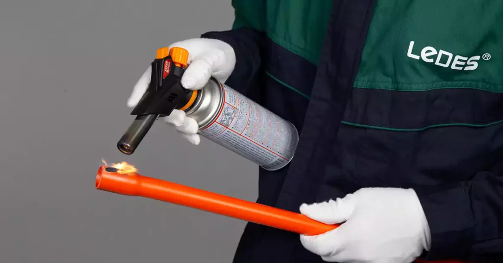
The resistance to burning test ensures that non-metallic and composite conduits and fittings exhibit sufficient resistance to flame propagation. This assessment is crucial for identifying materials that can prevent or limit the spread of fire in electrical installations. Products that pass this test are classified as non-flame propagating, enhancing safety in fire-sensitive environments.
Key Test Overview
This test is conducted using a 1 kW flame in accordance with AS/NZS 4695.2.41 and involves:
- Measuring the ignitability and flame propagation properties of representative samples.
- Evaluating fittings of similar material and design under equivalent conditions.
- Exempting small fittings from testing due to negligible impact on flame behavior.
Apparatus Required
The test setup includes:
- Test Enclosure:
A rectangular metal enclosure with an open face to control environmental variables and minimize draughts.
- Mounting Components:
Metal clamps and steel rods to position conduits and fittings securely.
- Tissue Paper and Pinewood Board:
A layer of white tissue paper (mass of 12–25 g/m²) placed over a pinewood board at the bottom of the enclosure to detect falling molten material.
- 1 kW Burner:
Positioned at a 45 ±2° angle to simulate flame exposure under controlled conditions.
Test Pieces
The test is carried out on three samples:
导管:
A 675 ±10 mm length is mounted vertically using two clamps, spaced 550 ±10 mm apart.
Testing Procedure
The test involves the following steps:
- 安装:
Secure the sample vertically in the enclosure using clamps or suspension.
- Flame Application:
Direct the burner flame at a 45° angle onto the sample for 60 ±1 seconds.
Ensure the flame intersects the surface of the sample at specified points based on the type of test piece.
- Observation:
Monitor flame behavior and any material fallout during the test.
- Post-Test Inspection:
Allow the sample to cool.
Wipe the surface with a water-soaked cloth to remove soot and assess damage.
Acceptance Criteria
A sample passes the resistance to burning test if:
- It does not ignite during flame application.
- Burning or charring is absent within 50 mm of the upper and lower clamps after wiping.
- Combustion ceases within 30 seconds after flame removal.
- Tissue paper at the enclosure’s base remains unignited.
- Molten material present on the sample’s surface does not result in burning or charring.
电气特性
Insulating: The conduit must offer high electrical insulation to protect cables and prevent accidental contact with conductive elements.
外部影响
耐腐蚀性: Materials must resist degradation from moisture, chemicals, and soil.
电磁兼容性 (EMC)
Ensures the conduit does not interfere with or become affected by electromagnetic fields.
AS/NZS 2053.5 – Corrugated Conduits and Fittings
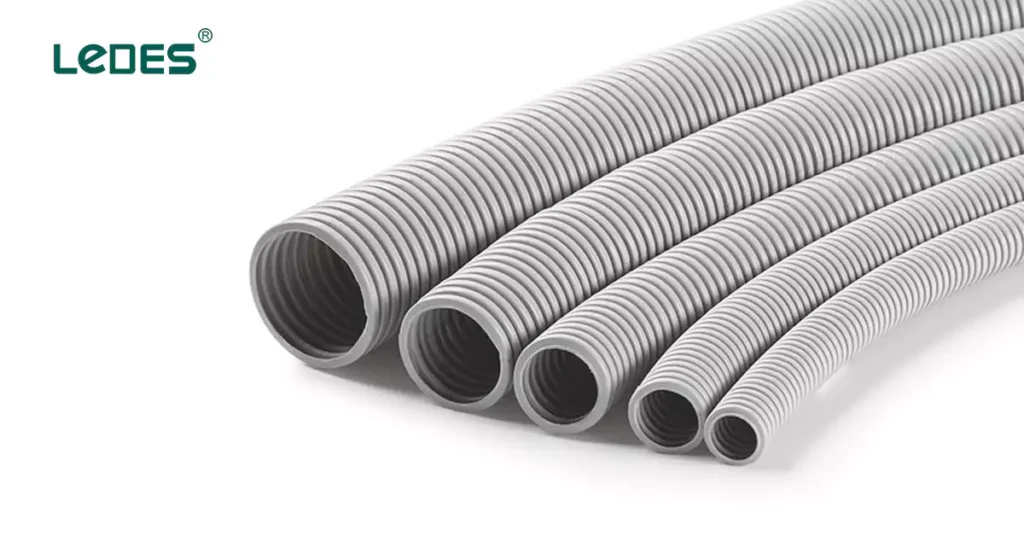
The AS/NZS 2053.5 standard defines the requirements for non-threadable corrugated conduits and their associated fittings made of insulating materials. These conduits are used to protect electrical cables in installations, offering flexibility, mechanical protection, and resistance to external influences. This standard is closely linked to AS/NZS 2053.1, which provides general requirements and guidelines.
Scope and Applicability
This standard applies to:
- Non-threadable corrugated conduits of insulating materials.
- Fittings specifically designed to be used with corrugated conduits.
- Electrical installations requiring cable protection under varying environmental and mechanical conditions.
分类
Corrugated conduits and fittings are classified based on the following, these are what applicable for AS/NZS 2053.5:
According to mechanical properties:
轻型
中型
重负
According to flame propagation:
Non-flame propagating
Electrical Characteristics:
Ability to provide electrical insulation and prevent continuity issues.
Dimensions of corrugated conduits
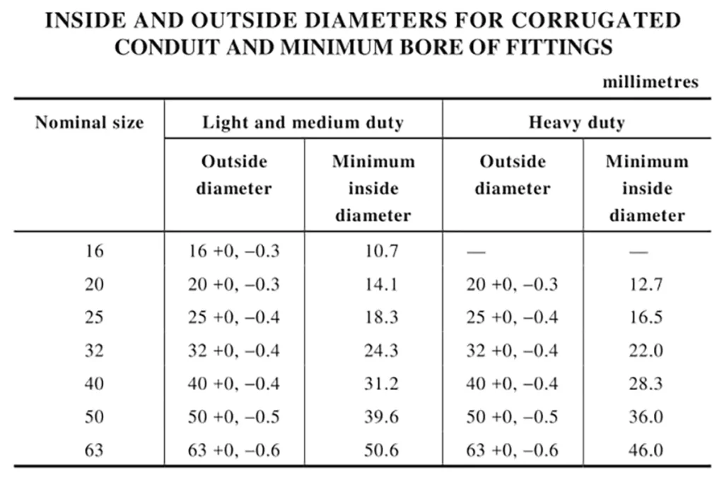
The standard specifies nominal diameters, wall thicknesses, and tolerances for corrugated conduits.
机械性能
The following mechanical tests ensure corrugated conduit performance under stress:
Bending Test:

The bending test outlined in AS/NZS 2053.5 ensures that non-threadable corrugated conduits can withstand mechanical stress during installation and use. This test evaluates the conduit’s ability to maintain its structural integrity and functionality when subjected to repetitive bending movements at both standard and low-temperature conditions.
Test Pieces
- Six test pieces are required, each with a length of at least 12 times their outside diameter.
- Three samples are tested at 20°C, while the remaining three are tested at the manufacturer-specified lowest installation temperature.
Test Procedure
- Test at 20°C
(a) Conditioning:
Place the test piece and apparatus in the conditioning chamber for 2 hours at 20°C ±1°C.
(b) Bending Process:
Perform the following sequence by hand:
Bend the test piece 90° to the left.
Return it to the vertical position.
Bend the test piece 90° to the right.
Return it to the vertical position.
Hold the position for 1 minute after each step.
Repeat the sequence 4 times, but on the final cycle, stop at 90° to the right and hold the position for 5 minutes.
(c) Gauge Test:
Rotate the bending apparatus to align the straight sections of the test piece at a 45° angle to the vertical.
Pass the diameter gauge through the conduit under its own weight, ensuring no initial velocity is applied.
- Test at Lowest Installation Temperature
(a) Conditioning:
Place the test piece and apparatus in the conditioning chamber for 2 hours at the manufacturer-specified lowest installation temperature ±2°C.
(b) Repeat Bending Sequence:
Follow the same bending steps and gauge test outlined for 20°C testing.
Criteria for Acceptance
A conduit passes the bending test if:
The gauge passes through the conduit under its own weight without any applied force.
There are no visible cracks on the test piece observed with normal or corrected vision, without magnification.
Compression Resistance:
The Compression Resistance Test as specified in AS/NZS 2053.5 evaluates the ability of corrugated conduits and fittings to resist deformation when subjected to compressive forces. The procedure follows the same methodology outlined for rigid plain conduits in AS/NZS 2053.2, but the acceptance criteria requirement is different.
For corrugated conduits: The difference between the initial outside diameter and the diameter measured under compression does not exceed 25% of the initial diameter.
Collapse Test:
The collapse test procedure of corrugated conduit is the same as rigid plain conduit, which all test according to AS/NZS 2053.1.
And the corrugated conduit passes the collapse resistance test if:
The specified gauge passes through the minimum internal diameter of the conduit after conditioning, confirming that the internal space remains unobstructed.
Flexing Test:
The Flexing Test, as outlined in AS/NZS 2053.5, assesses the durability and mechanical resilience of corrugated conduits and their terminating fittings when subjected to repeated bending movements. This test ensures that the conduits can endure dynamic mechanical stresses encountered during installation or in service without compromising their structural integrity or functionality.
Test Procedure
安装:
Fix the test piece to the oscillating member of the apparatus by its terminating fitting.
Align the conduit so that, at the midpoint of its travel, its axis is vertical and passes through the axis of oscillation.
Flexing Motion:
Subject the test piece to 5000 flexings at a rate of 40 flexings per minute.
Each flexing involves a full cycle of movement, starting from the vertical position and moving backwards and forwards through an angle of 180°.
Inspection:
After completing the test, inspect the test piece for structural damage using normal or corrected vision, without magnification.
Acceptance Criteria
There are no visible signs of structural damage upon inspection with normal or corrected vision.
Resistance to Heat:
Test Procedure
Heat Conditioning:
Place the test piece and heat test apparatus in the conditioning chamber.
Maintain the specified highest installation temperature for 4 hours.
Load Application:
Apply a load through a 6 mm steel rod, positioned as perpendicular as possible to the conduit’s axis, as shown in bellow.
Load for Resistance to Heat Test of AS/NZS 2053.5
导管 | Mass kg |
光 | 1.0 |
中等的 | 2.0 |
重的 | 4.0 |
冷却:
After 24 hours, remove the test piece and apparatus from the chamber and allow them to cool to room temperature.
Gauge Test:
Remove the load and attempt to pass the appropriate gauge through the test piece under its own weight, without any initial velocity, with the conduit in a vertical position.
Acceptance Criteria
The test piece passes if:
The gauge successfully passes through the conduit under its own weight, without any additional force or velocity.
Resistance to Burning:
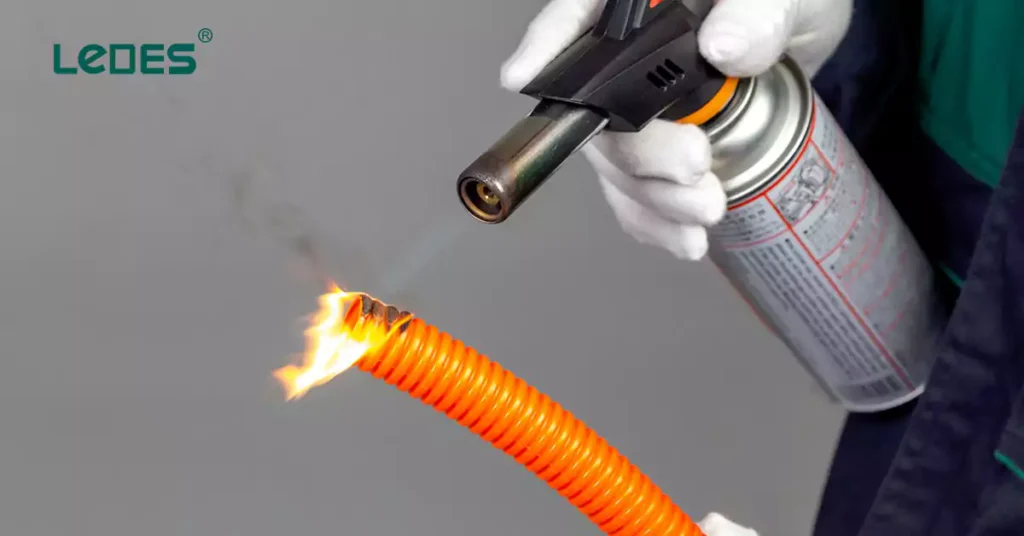
The burning resistance test of corrugated conduits is same as rigid plain conduit. With same requirements.
Electrical Characteristic
Electrical Continuity: Not applicable
Insulating: Same requirements as rigid plain conduit in AS/NZS 2053.2.
外部影响
Same requirements as rigid plain conduit in AS/NZS 2053.2.
Electromagnetic Compatibility
Same as rigid plain conduits in AS/NZS 2053.2
AS/NZS 2053.6 - Profile-Wall, Smooth-Bore Conduits and Fittings
AS/NZS 2053.6 specifies the requirements for rigid, non-threadable, profile-wall, smooth-bore conduits and fittings made from insulating materials. These conduits are designed for protecting cables in electrical installations and are available in designated sizes ranging from 90 mm to 150 mm.
定义
Profile-wall, smooth-bore conduits: Conduits with a smooth inner surface for easy cable insertion and a profile wall (which may be hollow) for strength. These conduits are typically not intended for bending.
Classification according to Mechanical Strength:
Light Duty
中型
重负
Dimensions of Conduits
The dimensions of conduits are controlled to ensure compatibility with associated fittings. The specified diameters, socket dimensions and tolerances ensure both mechanical stability and electrical performance.
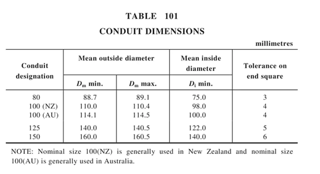
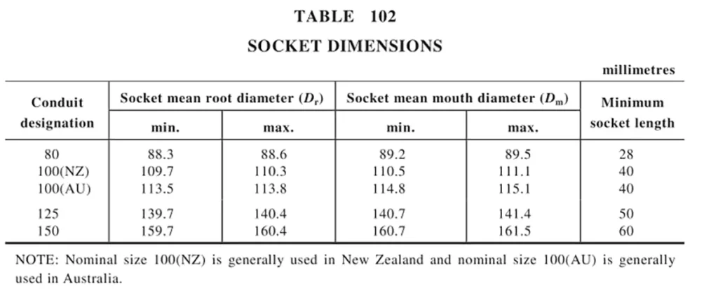
机械性能
AS/NZS 3053.6 lists the mechanical strength requirements for the Profile-wall, smooth-bore conduits and fittings, details as follows:
Compression Resistance:
The conduits compression test and requirements are similar as rigid plain conduits and corrugated conduits, all tested according to AS/NZS 2053.1. But for profile-wall, smooth-bore conduits, the difference between the initial outside diameter and the diameter measured with the force still applied should not exceed 25%.
The other mechanical strength test for profile-wall, smooth-bore conduits are not applicable, such as: bending, collapse, impact, pull-out strength of joints tests.
Resistance to Heat
The conduits are tested to ensure structural stability at the highest installation temperature specified by the manufacturer. Testing includes exposure to the designated temperature for 4 hours under specified load conditions:
程序:
- Place the test piece and apparatus in the conditioning chamber.
- Maintain the chamber at the highest installation temperature (±2°C) for 4 hours.
- Apply the load using a 6 mm steel rod as specified in Table AA1.
- After 24 hours, remove the test piece and allow it to cool to room temperature.
- Test if the gauge passes through the conduit under its own weight.
Acceptance Criterion:
The conduit passes if the gauge moves freely through without resistance.
Resistance to Burning
The materials must exhibit flame retardant properties. Tests ensure that the conduit resists ignition and self-extinguishes after removal of the flame source. Flammability ratings are determined in accordance with AS/NZS 2053.1, same like rigid plain conduits and corrugated conduits.
电气特性
Electrical Continuity: Not applicable
Insulating: Same as rigid plain conduits and corrugated conduits
外部影响
Same as rigid plain conduits and corrugated conduits except that, Conduits and fittings of insulating material are classified as having high protection (inside and outside) against corrosive and polluting substances and need not be tested.
Electromagnetic Compatibility
Same as rigid plain conduits and corrugated conduits
Case Study
At Ledes, our commitment to excellence is reflected in every step of the production process for our Australian Standard rigid conduits and corrugated conduits. By aligning with the stringent requirements of standards like AS/NZS 2053.2 and AS/NZS 2053.5, we ensure that our products consistently deliver superior performance, durability, and safety across diverse applications.
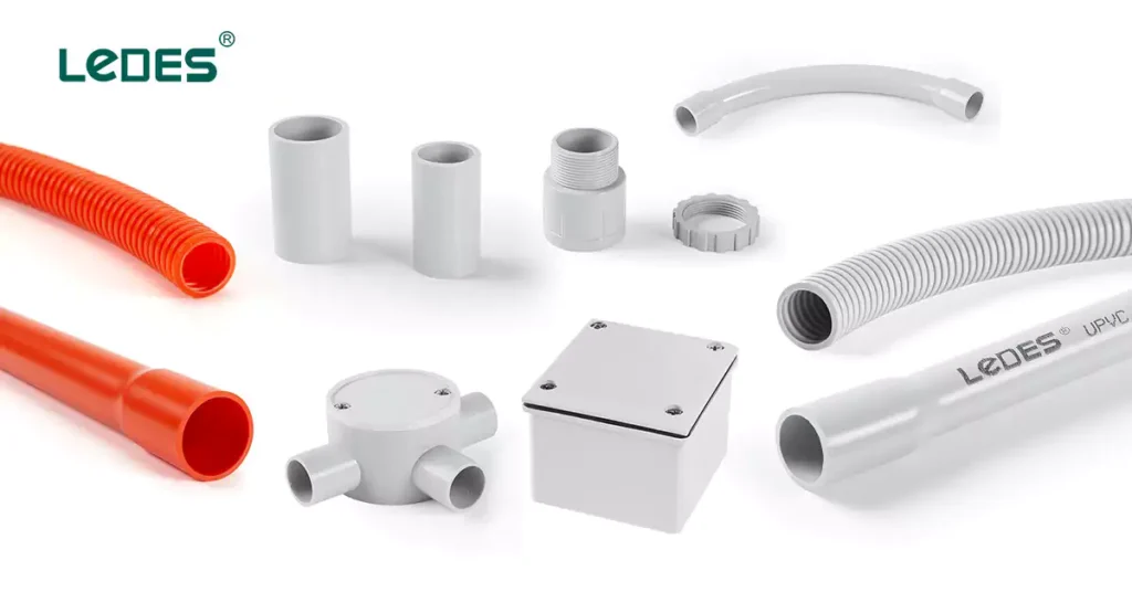
Ledes AS/NZS 2053 Certified Electrical Conduit & Fittings
Our product portfolio includes:
Heavy-Duty Rigid Conduits: Built for high mechanical stress environments, offering superior compression and impact resistance.
Medium-Duty Rigid Conduits: Lightweight yet durable solutions for less demanding applications.
Medium-Duty Communication Rigid Conduits: Lightweight and suitable for communication systems.
Heavy-Duty Corrugated Conduits: Flexible, strong, and capable of withstanding harsh environmental conditions.
Medium-Duty Corrugated Conduits: Ideal for dynamic applications requiring easier handling and installation.
Medium-Duty Communication Corrugated Conduits: For communication applications.
配件: Engineered to ensure secure and reliable connections, including bends, couplings, adaptors, and junction boxes etc.
Advantages of Ledes Australian Standard Conduits and Fittings
All Ledes conduits and fittings are manufactured to align with AS/NZS 2053 standards, offering key benefits such as:
Mechanical Strength: Excellent resistance to compression, impact, and deformation under load, ensuring durability in both underground and exposed installations.
Thermal Performance: Stability at high installation temperatures, maintaining structural integrity even under prolonged exposure to heat.
阻燃性: Rigid and corrugated conduits meet flame-resistance requirements, with options for Low Smoke Halogen-Free (LSZH) materials that reduce toxic emissions during a fire.
安装简便: Smooth bore for easy cable pulling and profile-wall construction for enhanced strength.
Environmental Resistance: High resistance to UV exposure, moisture, and corrosive substances, making them ideal for outdoor and industrial applications.
Quality Control at Ledes
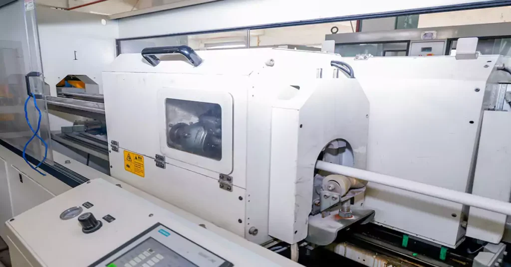
At Ledes, we believe that superior products begin with strict quality control measures at every stage:
1. Raw Material Selection:
- Only premium-grade PVC and insulating materials are used to ensure compliance with mechanical, thermal, and electrical performance standards.
- Raw materials undergo thorough testing for purity, composition, and consistency.
- Low Smoke Halogen-Free (LSZH) Options: To cater to projects with heightened safety demands, such as subway systems, we also offer LSZH conduits and fittings that minimize smoke and toxic gas emissions during fires.
2. Precision Manufacturing:
At Ledes, precision manufacturing is the cornerstone of our ability to produce high-performance Australian Standard conduits and fittings. Our state-of-the-art production process ensures each product meets the rigorous demands of AS/NZS 2053 standards. Key highlights of our manufacturing process include:
- Advanced Extrusion Technology
Precision Extrusion:
Using cutting-edge extrusion machines, we produce rigid and corrugated conduits with consistent wall thickness, dimensional accuracy, and a smooth internal bore.
This precision ensures seamless cable pulling and eliminates risks of cable abrasion during installation.
Profile-Wall Construction:
For corrugated conduits, our extrusion process incorporates a reinforced profile-wall structure. This combines flexibility with high mechanical strength, making the conduits suitable for dynamic environments and tight installation spaces.
Controlled Cooling Systems:
After extrusion, conduits pass through controlled cooling tanks to solidify their structure without internal stress, ensuring long-term durability and resistance to environmental factors.
Automated Fitting Production
Injection Molding for Fittings:
Our fittings, including couplings, adaptors, and junction boxes, are manufactured using high-precision injection molding machines.
This process guarantees tight tolerances, smooth edges, and secure fitment, ensuring compatibility with all Ledes conduits and compliance with AS/NZS standards.
- Real-Time Monitoring and Adjustments
Computerized Monitoring Systems:
Throughout the production process, real-time monitoring systems control variables like temperature, pressure, and extrusion speed to ensure uniform quality across all batches.
Any deviations are flagged immediately, and adjustments are made to maintain precision.
Batch Coding and Traceability:
Each batch of product is coded for traceability, enabling thorough quality assurance and ensuring that every product delivered to our clients meets strict specifications.
- Post-Manufacturing Finishing
Cutting and Chamfering:
Conduits are precision-cut to ensure clean ends and uniform lengths, facilitating easier installation. For rigid conduits, chamfering is applied to the ends for a snug fit with fittings.
End-Bell Formation:
For rigid conduits, end-bell formations are produced during the extrusion process to ensure quick and secure connections without additional accessories.
Custom Lengths and Packaging:
We offer customizable lengths and professional packaging to meet project-specific requirements, reducing waste and installation time for contractors.
3. Rigorous Testing:
We select samples from every production batch for testing, replicating the procedures outlined in AS/NZS 2053. These tests include:
Compression resistance
Collapse test
Heat resistance
Flame retardancy
The Melbourne Tunnel Project: A Success Story
The Melbourne Tunnel Project is a landmark infrastructure initiative aimed at enhancing Melbourne’s urban transit system by delivering a world-class underground rail network. Designed to alleviate congestion and improve connectivity, the project involves constructing twin 9-kilometer tunnels, state-of-the-art stations, and advanced systems to support high-capacity rail services. With stringent safety and environmental standards, the project represents a monumental leap in Australia’s commitment to sustainable and efficient public transport.
Ledes’ Conduits and Fittings in the Project
Ledes proudly supplied Australian Standard rigid conduits, corrugated conduits, and fittings for the Melbourne Tunnel Project. These components played a pivotal role in ensuring the safety, reliability, and efficiency of the electrical installations within this critical infrastructure.
The key products selected for this project are Ledes’ Low smoke halogen free conduits and fittings, due to excellent fire resistance, low toxicity, and durability, they play a crucial role in the project to ensure meet stringent requirements for electrical safety, reliability, and environmental performance.
The conduits were instrumental in protecting critical cabling systems from mechanical damage, external influences, and fire risks, making them an essential component of this ambitious project.
How to Choose the Right Electrical Conduit Supplier?
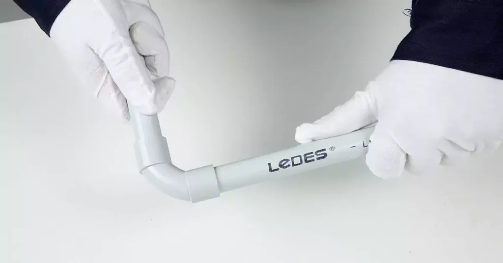
There are 8 pro tips for choosing the right PVC conduit supplier in Australia and New Zealand,
- Compliance with Standards: Ensure the supplier’s products meet Australian Standards (e.g., AS/NZS 2053, IEC 61386) and local building codes.
- Certification and Testing: Verify that the supplier provides certifications and test reports proving compliance with regulatory requirements.
- Proven Project Experience: Look for suppliers with a track record in major local infrastructure projects, demonstrating reliability and adherence to standards.
- 质量保证: Evaluate their quality control processes, including raw material sourcing, production monitoring, and batch testing for consistent product quality.
- 产品范围: Choose a supplier with a comprehensive product portfolio, including rigid and corrugated conduits, low-smoke halogen-free options, and various fittings.
- 技术支援: Consider suppliers that offer technical guidance, installation support, and customized solutions to meet project-specific needs.
- Timely Delivery: Prioritize suppliers with a reliable distribution network and the ability to meet project deadlines.
- Price vs. Value: While price is important, focus on overall value, including product durability, compliance, and reliability. A slightly higher upfront cost may save on replacements and maintenance in the long run.
结论
The AS/NZS 2053 series establishes a comprehensive framework for electrical conduit systems, ensuring safety, performance, and compliance with Australian and New Zealand standards. By understanding the requirements of these standards and choosing products that meet their rigorous criteria, you can achieve reliable and high-quality installations.
At Ledes, we are dedicated to providing Australian Standard conduits and fittings that combine precision manufacturing, stringent quality control, and proven performance. Whether for critical infrastructure projects or everyday applications, our solutions ensure compliance, safety, and durability.
For more information about our products or to discuss your project needs, contact us today.


