Índice
PVC Conduit Fill Chart – a crucial tool in the world of electrical installations. In this comprehensive tutorial, we delve deep into understanding and utilizing this essential resource of PVC RIGID CONDUIT and ENT for electrical professionals and enthusiasts alike.
By the end of this article, you will get to know:
How to interpret and use a PVC Conduit Fill Chart effectively for various electrical projects.
The significance of conduit fill calculations in ensuring safety and compliance.
Practical tips and best practices for optimizing conduit fill in your installations.
Common mistakes to avoid when using a PVC Conduit Fill Chart.
Real-world examples demonstrating the application of conduit fill calculations in different scenarios.
The PVC Conduit Fill Chart is a tool used in electrical installations to determine the maximum number of wires that can be safely accommodated within rigid PVC conduit based on the National Electrical Code standards. This chart simplifies the process of calculating conduit fill by providing guidelines for different conduit sizes and wire types, helping ensure compliance with safety regulations and efficient utilization of conduit space in electrical projects. By referencing the PVC Conduit Fill Chart, electricians can make informed decisions about the capacity of PVC conduit for housing THWN or THHN wires, optimizing the installation process and promoting safety in electrical systems.
ENT (Electrical Nonmetallic Tubing) and rigid PVC conduit are two widely used conduit type in electrical systems, providing protection and routing for electrical wiring.
ENT is a lightweight, non-metallic conduit designed for residential and light commercial applications. It is easy to install and resistant to corrosion, making it a popular choice for various wiring projects.
Conduíte de PVC rígido is a durable and weather-resistant option for electrical installations, commonly used in outdoor and underground applications. It offers excellent protection for wires and cables against environmental elements.
Código Elétrico Nacional (NEC): The NEC sets the safety standards for electrical installations in the United States, including regulations for conduit types and installation practices.
UL (Underwriters Laboratories) Listing: Conduits should be UL-listed, indicating that they meet safety and performance standards set by UL.
NEMA (National Electrical Manufacturers Association) Standards: NEMA provides standards for electrical products, including conduits, to ensure consistency and quality in manufacturing.
Here is an introduction to the common types of wires installed in conduit:
Introduction: THHN (Thermoplastic High Heat-resistant Nylon-coated) and THWN (Thermoplastic Heat and Water-resistant Nylon-coated) wires are versatile and widely used in conduit installations.
Characteristics: Known for their heat and moisture resistance, these wires are suitable for various applications in residential, commercial, and industrial settings.
Introduction: XHHW (Cross-linked polyethylene High Heat-resistant Water-resistant) wire is a popular choice for conduit installations due to its robust thermal and chemical resistance.
Characteristics: Ideal for both indoor and outdoor use, XHHW wire provides reliable performance in demanding environments.
Introduction: THW (Thermoplastic Heat and Water-resistant) wire is a dependable choice for conduit installations, offering resistance to moisture and versatility in wet locations.
Characteristics: THW wire is known for its durability and reliability, making it a preferred option for various electrical wiring applications.
Introduction: THHW wire is a type of electrical wire commonly used in conduit installations for various applications.
Characteristics: THHW wire is designed to withstand high heat (H), moisture (W), and resistance to oil (O). This makes it suitable for use in both dry and damp locations, providing reliable performance in a range of electrical wiring setups.
Introduction: RHH (Thermoset High Heat-resistant) and RHW (Thermoset Heat-resistant Water-resistant) wires are chosen for conduit installations due to their high-temperature resistance and durability.
Characteristics: These wires excel in harsh environments, offering reliable performance where high heat and environmental factors are concerns in conduit applications.
The PVC Conduit Fill Table provides guidelines for determining the maximum number of conductors that can be safely installed in a PVC conduit of a specific size. This table is used to ensure that the conduit is not overfilled, which can lead to overheating and pose a fire hazard.
The National Electrical Code (NEC) sets standards for conduit fill to prevent overheating and maintain safe operating conditions for electrical installations. Adhering to the conduit fill table helps electricians and installers comply with NEC regulations and maintain the integrity of the electrical system.
The table typically lists different conduit sizes and the corresponding maximum number of conductors allowed based on their sizes and insulation types. By referencing the PVC Conduit Fill Table, electricians can determine the appropriate conduit size for a given number and size of conductors, ensuring compliance with safety regulations and preventing potential hazards.
In this article, we’ll mainly introduce about PVC conduit, Schedule 40 and schedule 80 rigid PVC conduit and Electrical Nonmetallic Tubing’s fill chart.
ENT Conduit Fill Chart | |||||||||||||||||||||
| ENT Trade Size (Inches) | Wire Conductor Size AWG/kcmil (THWN,THWN-2, THHN) | ||||||||||||||||||||
| 14 | 12 | 10 | 8 | 6 | 4 | 3 | 2 | 1 | 1/0 | 2/0 | 3/0 | 4/0 | 250 | 300 | 350 | 400 | 500 | 600 | 700 | 750 | |
| 1⁄2 | 11 | 8 | 5 | 3 | 1 | 1 | 1 | 1 | 1 | 1 | |||||||||||
| 3⁄4 | 21 | 15 | 9 | 5 | 4 | 2 | 1 | 1 | 1 | 1 | 1 | 1 | 1 | ||||||||
| 1 | 34 | 25 | 15 | 9 | 6 | 4 | 3 | 3 | 1 | 1 | 1 | 1 | 1 | 1 | 1 | 1 | |||||
| 1-1⁄4 | 60 | 43 | 27 | 16 | 11 | 7 | 6 | 5 | 3 | 3 | 2 | 1 | 1 | 1 | 1 | 1 | 1 | 1 | 1 | ||
| 1-1⁄2 | 82 | 59 | 37 | 21 | 15 | 9 | 8 | 7 | 5 | 4 | 3 | 3 | 2 | 1 | 1 | 1 | 1 | 1 | 1 | 1 | 1 |
| 2 | 135 | 99 | 62 | 36 | 26 | 16 | 13 | 11 | 8 | 7 | 6 | 5 | 4 | 3 | 3 | 2 | 1 | 1 | 1 | 1 | 1 |
Schedule 40 & 80 Rigid PVC Conduit Fill Table | ||||||||||||||||||||||||
| Conduit Trade Size(Inches) | Wire Conductor Size AWG/kcmil (THWN,THHN) | |||||||||||||||||||||||
| 14 | 12 | 10 | 8 | 6 | 4 | 3 | 2 | 1 | 1/0 | 2/0 | 3/0 | 4/0 | 250 | 300 | 350 | 400 | 500 | 600 | 700 | 750 | 800 | 900 | ||
| 1⁄2 | Sch 40 | 11 | 8 | 5 | 3 | 1 | 1 | 1 | 1 | 1 | 1 | |||||||||||||
| Sch 80 | 9 | 6 | 4 | 2 | 1 | 1 | 1 | 1 | ||||||||||||||||
| 3⁄4 | Sch 40 | 21 | 15 | 9 | 5 | 4 | 2 | 1 | 1 | 1 | 1 | 1 | 1 | 1 | ||||||||||
| Sch 80 | 17 | 12 | 7 | 4 | 3 | 1 | 1 | 1 | 1 | 1 | 1 | 1 | ||||||||||||
| 1 | Sch 40 | 34 | 25 | 15 | 9 | 6 | 4 | 3 | 3 | 1 | 1 | 1 | 1 | 1 | 1 | 1 | 1 | |||||||
| Sch 80 | 28 | 20 | 13 | 7 | 5 | 3 | 3 | 2 | 1 | 1 | 1 | 1 | 1 | 1 | ||||||||||
| 1-1⁄4 | Sch 40 | 60 | 43 | 27 | 16 | 11 | 7 | 6 | 5 | 3 | 3 | 2 | 1 | 1 | 1 | 1 | 1 | 1 | 1 | 1 | ||||
| Sch 80 | 51 | 37 | 23 | 13 | 9 | 6 | 5 | 4 | 3 | 2 | 1 | 1 | 1 | 1 | 1 | 1 | 1 | 1 | ||||||
| 1-1⁄2 | Sch 40 | 82 | 59 | 37 | 21 | 15 | 9 | 8 | 7 | 5 | 4 | 3 | 3 | 2 | 1 | 1 | 1 | 1 | 1 | 1 | 1 | 1 | 1 | 1 |
| Sch 80 | 70 | 51 | 32 | 18 | 13 | 8 | 7 | 6 | 4 | 3 | 3 | 2 | 1 | 1 | 1 | 1 | 1 | 1 | 1 | 1 | 1 | 1 | ||
| 2 | Sch 40 | 135 | 99 | 62 | 36 | 26 | 16 | 13 | 11 | 8 | 7 | 6 | 5 | 4 | 3 | 3 | 2 | 1 | 1 | 1 | 1 | 1 | 1 | 1 |
| Sch 80 | 118 | 86 | 54 | 31 | 22 | 14 | 12 | 10 | 7 | 6 | 5 | 4 | 3 | 3 | 2 | 1 | 1 | 1 | 1 | 1 | 1 | 1 | 1 | |
| 2-1⁄2 | Sch 40 | 193 | 141 | 89 | 51 | 37 | 22 | 19 | 16 | 12 | 10 | 8 | 7 | 6 | 4 | 4 | 3 | 3 | 2 | 1 | 1 | 1 | 1 | 1 |
| Sch 80 | 170 | 124 | 78 | 45 | 32 | 20 | 17 | 14 | 10 | 9 | 7 | 6 | 5 | 4 | 3 | 3 | 3 | 2 | 1 | 1 | 1 | 1 | 1 | |
| 3 | Sch 40 | 299 | 218 | 137 | 79 | 57 | 35 | 30 | 25 | 18 | 15 | 13 | 11 | 9 | 7 | 6 | 5 | 5 | 4 | 3 | 3 | 2 | 2 | 2 |
| Sch 80 | 265 | 193 | 122 | 70 | 51 | 31 | 26 | 22 | 16 | 14 | 11 | 9 | 8 | 6 | 5 | 5 | 4 | 3 | 3 | 2 | 2 | 2 | 1 | |
| 3-1⁄2 | Sch 40 | 401 | 293 | 184 | 106 | 77 | 47 | 40 | 33 | 25 | 21 | 17 | 14 | 12 | 10 | 8 | 7 | 6 | 5 | 4 | 4 | 3 | 3 | 3 |
| Sch 80 | 358 | 261 | 164 | 95 | 68 | 42 | 35 | 30 | 22 | 18 | 15 | 13 | 10 | 8 | 7 | 6 | 6 | 5 | 4 | 3 | 3 | 3 | 3 | |
| 4 | Sch 40 | 517 | 377 | 238 | 137 | 99 | 61 | 51 | 43 | 32 | 27 | 22 | 18 | 15 | 12 | 11 | 9 | 8 | 7 | 5 | 5 | 4 | 4 | 4 |
| Sch 80 | 464 | 338 | 213 | 123 | 89 | 54 | 46 | 39 | 29 | 24 | 20 | 17 | 14 | 11 | 9 | 8 | 7 | 6 | 5 | 4 | 4 | 4 | 3 | |
| 5 | Sch 40 | 815 | 594 | 374 | 216 | 156 | 96 | 81 | 68 | 50 | 42 | 35 | 29 | 24 | 20 | 17 | 15 | 13 | 11 | 9 | 8 | 7 | 7 | 6 |
| Sch 80 | 736 | 537 | 338 | 195 | 141 | 86 | 73 | 61 | 45 | 38 | 32 | 26 | 22 | 18 | 15 | 13 | 12 | 10 | 8 | 7 | 7 | 6 | 6 | |
| 6 | Sch 40 | * | 859 | 541 | 312 | 225 | 138 | 117 | 98 | 73 | 61 | 51 | 42 | 35 | 28 | 24 | 21 | 19 | 16 | 13 | 11 | 11 | 10 | 9 |
| Sch 80 | * | 770 | 485 | 279 | 202 | 124 | 105 | 88 | 65 | 55 | 46 | 38 | 31 | 25 | 22 | 19 | 17 | 14 | 12 | 10 | 9 | 9 | 8 | |
Calculating conduit fill according to the National Electrical Code (NEC) is essential for ensuring that conduits are not overcrowded, which can lead to overheating and potential electrical hazards. Here are some considerations:
Identify the size of the conduit you are using. Common sizes include ½”, ¾”, 1″, up to 8” etc.
Consider the type and number of conductors(wires) you need to install in the conduit, each type of wire (THHN,NM, etc.) has specific characteristics, you need to check on the wire gauge and find the maximum number if wires that can be placed inside the conduit. For example, if you’re using three 12 AWG THHN wires, the size and type will affect the total area.
Use NEC book for the cross-sectional area of each conductor, here are the table of conductors’ cross-section area:
Type of Conductor | Size of Conductor (AWG or kcmil) | Diameter (in.) | Area (square in.) |
THHN, THWN | 14 | 0.111 | 0.0097 |
12 | 0.130 | 0.0133 | |
10 | 0.164 | 0.0211 | |
8 | 0.236 | 0.0366 | |
6 | 0.254 | 0.0507 | |
4 | 0.324 | 0.0824 | |
3 | 0.352 | 0.0973 | |
2 | 0.384 | 0.1158 | |
1 | 0.446 | 0.1562 | |
1/0 | 0.486 | 0.1855 | |
2/0 | 0.532 | 0.2223 | |
3/0 | 0.584 | 0.2679 | |
4/0 | 0.642 | 0.3237 | |
250 | 0.711 | 0.3790 | |
300 | 0.766 | 0.4608 |
12 AWG THHN has a cross-sectional area of approximately 0.0133 sq. in..
- For three cables, the total cross-sectional area is:
3×0.0133=0.0399 sq. In
For other number of wires and types are the same calculation, but refer to NEC of the wire’s cross-sectional area.
Based on NEC Table 1 (Chapter 9, Table 1), you can determine the maximum fill percentages:
Número de condutores | Todos os tipos de condutores |
1 | 53% |
2 | 31% |
Mais de 2 | 40% |
And use the cross-sectional area you calculated to determine the minimum size of conduit you can use.
- Each bend adds resistance and can affect the space available for wiring. The NEC provides guidelines on how many conductors can be placed in a conduit with bends.
- For example, if there are two 90-degree bends, the allowable fill is reduced.
All the data the requirements have specified in the NEC, just follow this calculation steps and considerations then you will find out the proper conduit size you could need, and install the electrical system that comply with the codes and regulations.
The Canadian Electrical Code (CEC) sets out the standards and regulations for electrical installations across Canada, ensuring safety and efficiency in electrical systems. One critical aspect of these installations is conduit fill, which pertains to the maximum number of conductors that can safely fit within a conduit. Here we take Rigid PVC Conduit and ENT as examples to find out their conduit fill specifications according to CEC.
Maximum Conduit Fill Percentages (CEC)
Number of conductors | Conductors (not lead-sheathed) | Conductors (lead sheathed) |
1 | 53% | 55% |
2 | 31% | 30% |
3 | 40% | 40% |
4 | 40% | 38% |
Over 4 | 40% | 35% |
Calculations:
Here are the tables according to CEC (Table 6 – Table 10) about the different fill conductors’ area and conduit area of rigid PVC conduit and ENT.
Internal diameter and cross-sectional area allowable fill at 40%
Trade Size(mm) | Conduíte de PVC rígido | Otorrinolaringologista | ||
ID mm | Area sq.mm | ID mm | Area sq.mm | |
16 | 14.57 | 66.69 | 14.58 | 66.78 |
21 | 19.77 | 122.79 | 19.66 | 121.43 |
27 | 25.4 | 202.68 | 25.37 | 202.2 |
35 | 31.75 | 316.69 | 33.73 | 357.42 |
41 | 38.1 | 456.04 | 39.57 | 491.91 |
53 | 50.8 | 810.73 | 51.18 | 822.91 |
63 | 61.3 | 1180.51 | ||
78 | 76.2 | 1824.15 | ||
91 | 88.4 | 2455.02 | ||
103 | 100.1 | 3147.88 | ||
129 | 125.9 | 4975.72 | ||
155 | 149.74 | 7045.04 | ||
200 | 199.39 | 12489.83 | ||
Dimensions of conductors for calculating conduit and tubing fill
Conductor Size, AWG or kcmil | R90XLPE* RW75XLPE* RW90XLPE* 600 V | R90XLPE* RW75XLPE* RW90XLPE* 1000 V | R90XLPE+ RW75XLPE+ R90EP+,RW75EP+ RW90XLPE+ EW90PE+ | |||
Class B | Class B | Class B | ||||
Dia,mm | Area, sq.mm | Dia, mm | Area, sq.mm | Dia, mm | Area, sq.mm | |
14 12 10 8 6 4 3 2 1 1/0 2/0 3/0 4/0 250 300 350 400 | 3.36 3.84 4.47 5.99 6.95 8.17 8.88 9.70 11.23 12.27 13.44 14.74 16.21 17.90 19.30 20.53 21.79 | 8.89 11.61 15.67 28.17 37.98 52.46 61.99 73.85 99.10 118.3 141.9 170.6 206.4 251.8 292.6 331.0 373.0 | 4.12 4.60 5.23 5.99 7.71 8.93 9.64 10.46 12.49 13.53 14.70 16.00 17.47 19.17 20.56 21.79 23.05 | 13.36 16.65 21.45 28.17 46.73 62.67 73.05 85.88 122.6 143.9 169.8 201.0 239.7 288.5 332.1 372.9 417.3 | 4.12 4.60 5.23 6.75 8.47 9.69 10.40 11.22 13.51 14.55 15.72 17.02 18.49 21.21 22.60 23.83 25.09 | 13.36 16.75 21.45 35.77 56.39 73.79 85.01 98.82 143.4 166.4 194.2 227.5 268.5 353.2 401.2 446.0 494.5 |
The CSA C22.1:21 Canadian Electrical Code has specified the cross-sectional area that allowed at different fill percentages, including 53%, 31%, and 40% for several different commonly used conduit types. It also states out dimensions of different types of conductors for calculating the conduit fill. Before your installation, make sure to check out the codes for conduit and wiring installation requirements.
In the US, Schedule 40 and 80, Electrical Nonmetallic Tubing are most widely used conduit types, here are the product size chart from Ledes.
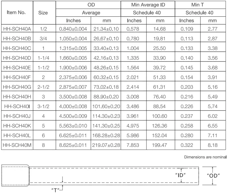
Ledes Schedule 40 rigid PVC conduit is UL651 certified, CSA C22.2 No211.2 approved and comply with NEMA TC-2, it is made of durable PVC, with excellent properties of sunlight resistant, impact resistant, flame retardant and corrosion resistant. Sizes ranging from 1/2” to 8”.
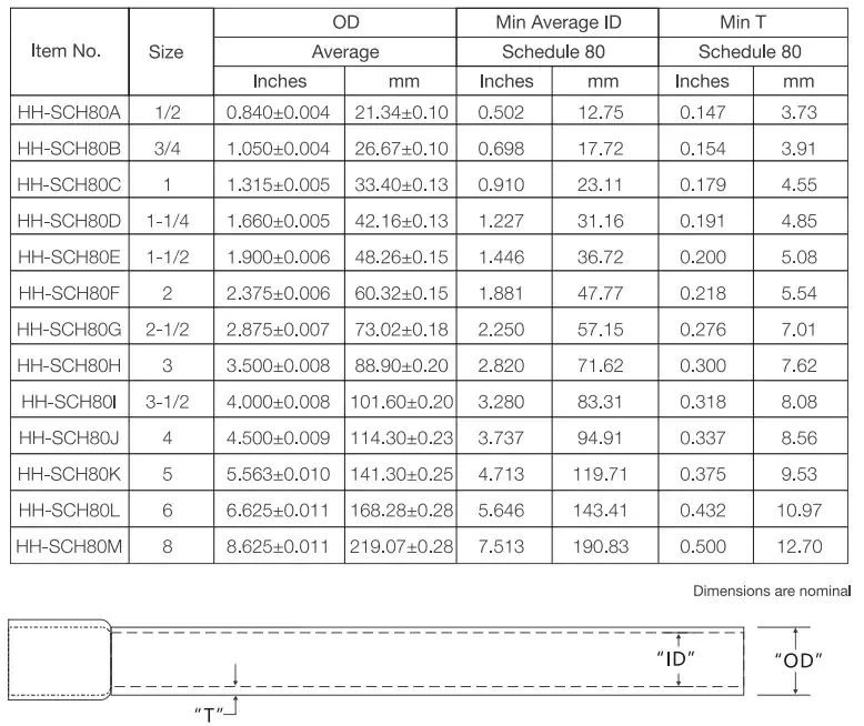
Ledes Schedule 80 rigid PVC conduit come in 1/2” to 8”, they are UL651 certified, and comply with NEMA TC-2, the conduits are corrosion resistant, impact resistant, and fire retardant, suitable for underground applications.
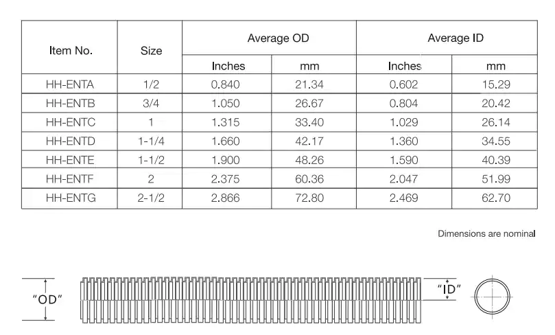
Ledes tubulação não metálica, ENT, come in 1/2” to 2-1/2”, UL and CUL certified to UL651 and CSA C22.2 No.227.1. The conduit is sunlight resistant, fire resistant, and impact resistant.
In this comprehensive tutorial, we explored the essential role of conduit fill in electrical installations, specifically focusing on PVC conduit. Understanding how to calculate conduit fill is critical for ensuring the safe and efficient operation of electrical systems, preventing overheating, and adhering to electrical codes. By referencing the PVC Conduit Fill Chart and following the fill guidelines for different conductor types and sizes, installers can determine the appropriate conduit size for their project, reducing the risk of overcrowding and ensuring long-term reliability.
By following the principles laid out in this guide and regularly consulting the PVC Conduit Fill Chart in the NEC and CEC, electricians and installers can ensure that their installations meet both practical needs and safety requirements, while optimizing performance.


