Inhaltsverzeichnis
Elektrische Leitungen spielen eine wichtige Rolle beim Schutz elektrischer Leitungen vor Beschädigungen und gewährleisten den sicheren und zuverlässigen Betrieb elektrischer Systeme. Ob in Wohn-, Gewerbe- oder Industrieanwendungen, elektrische Leitungen schützen die Verkabelung vor physischen Schäden, Feuchtigkeit, Feuer und anderen Umweltgefahren. Einer der wichtigsten Standards für die Verwendung und Installation von Elektroinstallationsrohre in Australien und Neuseeland ist AS/NZS 2053. Diese Norm enthält detaillierte Richtlinien zu den Typen, Materialien und Installationsverfahren für verschiedene Leitungssysteme und stellt sicher, dass sie die erforderlichen Sicherheits- und Leistungskriterien erfüllen.
In diesem umfassenden Leitfaden vertiefen wir uns in die drei wichtigsten AS/NZS 2053-Standards:
AS/NZS 2053.2–Leitungen und Armaturen für Elektroinstallationen–Starre, glatte Rohrleitungen aus Isoliermaterial.
AS/NZS 2053.6–Leitungen und Armaturen für Elektroinstallationen–Rohre und Formstücke mit glatter Profilwand aus Isoliermaterial.
AS/NZS2053.5 – Leitungen und Formstücke für elektrische Anlagen Teil 5 gewellte Leitungen und Formstücke aus Isoliermaterial
Wir werden ihren Umfang, ihre wichtigsten Bestimmungen und ihre Anwendung auf verschiedene Arten von elektrischen Leitungen, einschließlich starrer PVC-Leitungen, flexibler PVC-Leitungen und gewellter Leitungen, aufschlüsseln. Das Verständnis dieser Norm ist für Elektriker, Bauunternehmer und Ingenieure, die in diesen Regionen elektrische Systeme entwerfen, installieren oder warten, von entscheidender Bedeutung.
Durch das Lesen dieses Artikels erhalten Sie wertvolle Einblicke in Folgendes:
- Der Geltungsbereich der Norm AS/NZS 2053 und ihre Relevanz für verschiedene Arten von Leitungssystemen.
- Die verschiedenen Arten von Elektrorohren werden von der Norm abgedeckt, z. B. starre PVC-Rohre, PVC-Rohre, flexible PVC-Rohre und Wellrohre.
- Die Testverfahren, die Leitungsmaterialien durchlaufen müssen, um die erforderlichen Sicherheits- und Leistungsstandards zu erfüllen.
- Die Anwendung von AS/NZS 2053 in verschiedenen elektrischen Installationen und Umgebungen.
- Die Bedeutung der Einhaltung des AS/NZS-2053-Codes für die Gewährleistung sicherer und langlebiger elektrischer Systeme.
Hinweis: Der gesamte Inhalt dieses Artikels basiert auf der Version AS/NZS 2053 2001 und ist im Besitz von Standards Australia.
Standards Australia ist die nationale Normungsorganisation, die Normen für eine Vielzahl von Branchen in Australien entwickelt und veröffentlicht. Sie spielt eine entscheidende Rolle bei der Gewährleistung der Sicherheit, Qualität und Leistung von Produkten und Dienstleistungen, einschließlich elektrischer Systeme. Durch die Festlegung und Aktualisierung von Industrienormen stellt Standards Australia sicher, dass elektrische Anlagen den höchsten Sicherheits- und Zuverlässigkeitsstandards entsprechen und das Risiko elektrischer Gefahren verringert wird.
Der Standard AS/NZS 2053 ist das Ergebnis der Zusammenarbeit zwischen Standards Australia und Standards New Zealand. Er ist Teil eines umfassenderen Richtliniensatzes, der Einheitlichkeit und Konsistenz bei der Installation elektrischer Systeme in beiden Ländern gewährleisten soll. AS/NZS 2053 ist nicht nur für australische Elektriker und Ingenieure unverzichtbar, sondern dient auch als wichtige Referenz für elektrische Installationen in Neuseeland. Der Standard gilt für verschiedene Arten elektrischer Leitungen und bietet Richtlinien für deren Konstruktion, Installation und Prüfung, um sicherzustellen, dass sie die Sicherheits- und Leistungsanforderungen erfüllen.
Die Entwicklung von Elektronormen wie AS/NZS 2053 orientiert sich an internationalen Best Practices und berücksichtigt gleichzeitig die besonderen Anforderungen und Bedingungen der australischen und neuseeländischen Märkte. Die Einhaltung dieser Normen ist für die Einhaltung nationaler Bauvorschriften und -bestimmungen unerlässlich und gewährleistet so den Schutz sowohl elektrischer Systeme als auch der damit arbeitenden Personen.
Die Norm AS/NZS 2053 bietet umfassende Richtlinien für elektrische Leitungssysteme, sowohl metallische als auch nichtmetallische Leitungen und Armaturen, und stellt sicher, dass sie die Anforderungen an Sicherheit, Haltbarkeit und Leistung erfüllen. Der Geltungsbereich der Norm deckt verschiedene Aspekte von Leitungssystemen ab, darunter Materialien, Installationspraktiken und Testverfahren. Ihr Hauptziel besteht darin, elektrische Leitungen vor äußeren Einflüssen wie physischen Schäden, Feuchtigkeit, Feuer und chemischer Belastung zu schützen.
In diesem Abschnitt geht es um starre, glatte Leitungen, die einen robusten Schutz für elektrische Leitungen in festen Installationen bieten sollen.
Abgedeckte Leitungstypen:
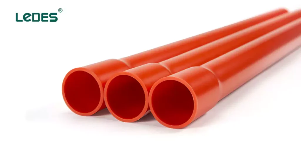
Starres PVC-Rohr: Ein weit verbreitetes Material aufgrund seines geringen Gewichts, seiner Korrosionsbeständigkeit, Flammhemmung und einfachen Installation. Diese Leitungen sind für freiliegende, eingebettete oder unterirdische Verkabelungssysteme geeignet.
Nicht flammenausbreitende Leitungen: Spezielle Leitungen sind darauf ausgelegt, die Flammenausbreitung im Brandfall zu minimieren und so die Gesamtsicherheit in Anlagen zu erhöhen.
Anwendungen:
Wand- und Deckeninstallationen im Wohn- und Gewerbebau.
Schutz unterirdischer Kabel in Infrastrukturprojekten.
Freiliegende Installationen, die UV-beständige und wetterfeste Lösungen erfordern.
Dieser Teil der Norm definiert vollständig gewellte Rohre, die leicht und hochflexibel sind und sich ideal für dynamische Installationen eignen, die Anpassungsfähigkeit erfordern.
Abgedeckte Leitungstypen:
PVC-Wellrohr: Aufgrund ihrer Anpassungsfähigkeit werden diese Leitungen häufig verwendet und eignen sich perfekt für die Installation in engen Räumen oder Bereichen mit häufigen Bewegungen.
UV-stabilisierte Wellrohre: Diese für den Außenbereich konzipierten Leitungen widerstehen UV-Strahlung und extremen Witterungsbedingungen.
Anwendungen:
Installation elektrischer Leitungen in engen oder beschränkten Räumen.
Dynamische Systeme, die häufigen Bewegungen ausgesetzt sind, wie etwa Roboter oder Maschinen.
Installationen im Außenbereich, die Beständigkeit gegen Umweltbelastungen erfordern.
Dieser Kabelkanaltyp verfügt über eine gewellte Außenwand für Flexibilität und Festigkeit sowie eine glatte Innenbohrung, um das Einziehen des Kabels zu erleichtern. Diese Kabelkanäle sind ideal für Installationen, die eine Kombination aus Anpassungsfähigkeit und Haltbarkeit erfordern.
Abgedeckte Leitungstypen wie:
Profilwand-PVC-Rohre: Mit gewellter Außenseite für mehr Flexibilität und Festigkeit, gepaart mit glatter Innenfläche für einfaches Kabelziehen.
Anwendungen:
Unterirdische Kabelverlegung in Versorgungsnetzen.
Flexible Installationen, die glatte Innenwände erfordern, um die Kabelreibung zu minimieren.
Infrastrukturprojekte in chemisch aggressiven Umgebungen.
AS/NZS 2053 ist vor allem für folgende Länder relevant:
Australien: Der Standard ist im ganzen Land anerkannt und übernommen und bildet die Grundlage für zahlreiche lokale Elektrovorschriften und Konformitätsanforderungen.
Neuseeland: Der Standard wird auch in Neuseeland anerkannt. Dadurch werden die Vorgehensweisen beider Länder angeglichen und sichergestellt, dass elektrische Anlagen ähnliche Sicherheits- und Leistungsstandards erfüllen.
Die AS/NZS 2053-Reihe ist ein Eckpfeiler der Normen für elektrische Leitungen in Australien und Neuseeland und bietet umfassende Anleitungen für Design, Konstruktion und Leistung von Leitungen und Armaturen für elektrische Installationen. Diese Normen gewährleisten Sicherheit, Zuverlässigkeit und Kompatibilität in unterschiedlichsten Anwendungen. In diesem Abschnitt fassen wir die wichtigsten Aspekte zusammen, die von den drei zuvor vorgestellten Hauptnormen abgedeckt werden: AS/NZS 2053.2, AS/NZS 2053.6 und AS/NZS 2053.5.
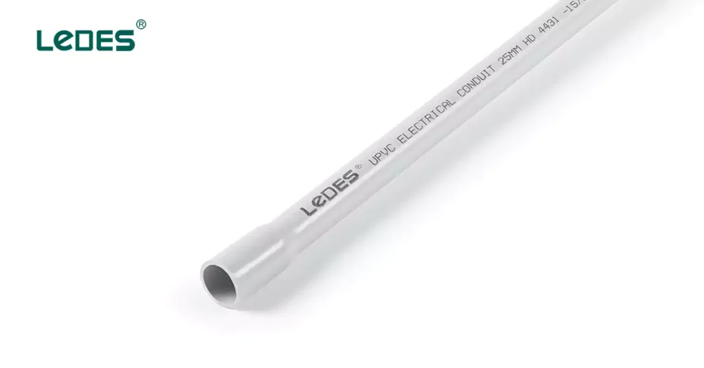
Diese Norm enthält detaillierte Spezifikationen für starre, glatte Leitungen für elektrische Anlagen. Sie beschreibt:
Materialbedarf: Normen für Isoliermaterialien wie PVC, die Haltbarkeit, elektrische Sicherheit und Beständigkeit gegen Umwelteinflüsse gewährleisten.
Maße: Spezifikationen für Durchmesser und Längen starrer Leitungen.
Mechanische Eigenschaften: Spezifikationen für Festigkeit, Druck- und Schlagfestigkeit, um verschiedenen Einsatzbedingungen gerecht zu werden.
Leistungstests: Kriterien zur Bewertung der Feuerbeständigkeit, der elektrischen Isolierung und der UV-Stabilität.
In diesem Teil der Serie werden die besonderen Merkmale von Wellrohren behandelt. Dabei wird Folgendes hervorgehoben:
Design-Spezifikationen: Die Rippenstruktur sorgt für erhöhte Flexibilität und Leichtbauweise.
Maße: Spezifikationen für Durchmesser und Längen starrer Leitungen.
Materialbedarf: Isoliermaterialien wie PVC, zugeschnitten auf hohe Flexibilität und Haltbarkeit.
Mechanische Eigenschaften: Kriterien für die Widerstandsfähigkeit gegen Stöße, Druck und dynamische Bewegungen.
Diese Norm konzentriert sich auf Leitungen mit einer außen profilierten Wand und einer glatten Innenbohrung. Sie umfasst:
Werkstoffnormen: Isoliermaterialien, die für flexible, leichte Leitungen geeignet sind.
Maßanforderungen: Spezifikationen für Wandprofile und Bohrglätte, um das einfache Einziehen des Kabels zu ermöglichen.
Mechanische und thermische Eigenschaften: Standards für Flexibilität, Schlagfestigkeit und Wärmestabilität.
AS/NZS 2053.2 ist ein wichtiger Standard der AS/NZS 2053-Reihe, der Anforderungen an starre, einfache, nicht gewindefähige Leitungen und Armaturen aus Isoliermaterial festlegt. Diese Leitungen werden hauptsächlich zum Schutz von Kabeln in elektrischen Anlagen verwendet und gewährleisten mechanischen Schutz und elektrische Sicherheit. Dieser Abschnitt bietet eine detaillierte Erläuterung des Standards, seiner Klassifizierungen, Abmessungen, mechanischen Eigenschaften und der zugehörigen Prüfverfahren.
AS/NZS 2053.2 gilt für:
Starre, einfache Leitungen: Nicht gewindefähig, aus isolierenden Materialien wie PVC.
Beschläge: Zubehör wie Kupplungen, Winkelstücke und Adapter sind für die Verwendung mit diesen Leitungen konzipiert.
Klassifiziert nach mechanische Eigenschaften:
- Vert leichtes starres Rohr
- Leichte starre Rohrleitung
- Starres Rohr für mittlere Beanspruchung
- Robustes starres Rohr
- Sehr robustes starres Rohr
Klassifiziert nach elektrische Eigenschaften:
- Mit elektrisch isolierenden Eigenschaften
Der Standard definiert präzise Maßanforderungen, um Kompatibilität und Einheitlichkeit zwischen den Installationen sicherzustellen.
Abmessungen des Rundrohrs (Größentabelle)
Nenngröße | Außendurchmesser | Wandstärke | ||||||||
Mittlerer Durchmesser | Sehr leichte Beanspruchung | Leichte Beanspruchung | Mittlere Beanspruchung | Schwere Ausführung | ||||||
Mindest. | Max. | Mindest. | Max. | Mindest. | Max. | Mindest. | Max. | Mindest. | Max. | |
16 | 15.7 | 16.0 | / | / | / | / | 1.6 | 1.9 | / | / |
20 | 19.7 | 20.0 | / | / | / | / | 1.8 | 2.1 | 2.3 | 2.6 |
25 | 24.7 | 25.0 | / | / | / | / | 1.8 | 2.1 | 2.5 | 2.8 |
32 | 31.7 | 32.0 | / | / | / | / | 2.1 | 2.4 | 2.7 | 3.0 |
40 | 39.7 | 40.0 | / | / | / | / | 2.4 | 2.7 | 3.1 | 3.4 |
50 | 49.7 | 50.0 | / | / | / | / | 2.8 | 3.1 | 3.4 | 3.9 |
63 | 62.7 | 63.0 | / | / | / | / | 3.0 | 3.5 | 3.9 | 4.5 |
65 | 75.2 | 75.5 | / | / | / | / | 3.0 | 3.5 | 3.9 | 4.5 |
80 (NZ) | 82.3 | 82.7 | / | / | 2.2 | 2.6 | 3.2 | 3.7 | 4.2 | 4.9 |
80 (AU) | 88.7 | 89.1 | 1.8 | 2.2 | 2.4 | 2.8 | 3.5 | 4.1 | 4.6 | 5.3 |
100 (NZ) | 110.0 | 110.4 | 2.2 | 2.6 | 2.9 | 3.4 | 4.3 | 5.0 | 5.7 | 6.5 |
100 (AU) | 114.1 | 114.5 | 2.3 | 2.7 | 3.0 | 3.5 | 4.5 | 5.2 | 5.9 | 6.7 |
125 | 140.0 | 140.4 | 2.8 | 3.3 | 3.7 | 4.3 | 5.5 | 6.3 | 7.2 | 8.1 |
150 | 160.0 | 159.5 | 3.2 | 3.7 | 4.2 | 4.8 | 6.3 | 7.1 | 8.3 | 9.3 |
Diagramm zur Leitungslänge
Größe des Rohres | Länge |
Bis Größe 63 | 4 m + 20, -0 mm |
Ab Größe 63 | 6 m + 50, -0 mm |
Die Norm legt strenge mechanische Leistungsanforderungen fest, um sicherzustellen, dass die Leitungen und Armaturen verschiedenen Belastungen standhalten:
Der in AS/NZS 2053.2 beschriebene Biegetest bewertet die mechanische Flexibilität und Haltbarkeit von Leitungen, die während der Installation oder Verwendung Biegekräften ausgesetzt sind. Der Test stellt sicher, dass Leitungen, die für bestimmte mechanische Belastungsstufen klassifiziert sind, dem Biegen ohne sichtbare Schäden standhalten und ihre Funktionalität und Integrität bewahren. Hier ist eine Zusammenfassung der in der Norm beschriebenen Anforderungen und Verfahren:
Anwendbarkeit
The bending test applies only to certain classifications and sizes of conduits:
Applicable Conduits:
Conduits with diameters less than 32 mm.
Those classified as suitable for:
Very light mechanical stress.
Light mechanical stress.
Medium mechanical stress.
Exempted Conduits:
Conduits with diameters equal to or greater than 32 mm.
Heavy-duty and very heavy-duty conduits, which are not required to undergo this test.
Test Procedure
The bending test involves the following steps:
- Platzierung:
Position the 500 mm test piece in the groove of the bending device, securing it lightly with the clamp.
- Bending:
Use the bending rollers to move the test piece around the former, creating a bend of approximately 180°.
After release, the test piece should retain a bend of 90°.
- Removal:
Remove the bending device without causing additional damage to the test piece.
Akzeptanzkriterien
After completing the test:
- The conduit must exhibit no cracks visible to normal or corrected vision without magnification.
- The conduit’s structural integrity must remain intact to ensure suitability for electrical installations.

The compression resistance test ensures that conduits can withstand compressive forces during installation and operational use without significant deformation or compromising structural integrity. This test evaluates how well a conduit maintains its shape and performance when subjected to specified loads.
Anwendbarkeit
The test applies to all conduits covered under AS/NZS 2053.2 and references the general compression resistance test outlined in Part 1 of the AS/NZS 2053. For a conduit to pass this test:
- The difference between the initial outside diameter and the diameter measured under applied force must not exceed 10%.
Test Pieces
- The test pieces consist of conduit sections cut to a length of 200 mm.
Test Procedure
The test is conducted in a controlled environment following these steps:
- Measurement and Conditioning:
Measure and record the initial outside diameter of the test piece.
Place the test piece in the conditioning chamber at 20°C ± 1°C for at least 10 hours.
- Compression Force Application:
Apply a compression force uniformly, ensuring it reaches the specified value within 30 ± 3 seconds.
Maintain the force for 60 ± 6 seconds.
- Measurement During Force:
While the force is applied, measure and record the outside diameter of the compressed section of the test piece.
- Post-Compression Measurement:
Remove the force and the intermediate piece.
After 1 minute, measure the outside diameter of the test piece at the point of applied force.
- Calculation:
The difference between the initial diameter and the diameter under applied force.
The difference between the initial diameter and the diameter measured after force removal.
Compression Force Data Sheet
Conduits | Compression force N |
Very light | 125 |
Light | 320 |
Medium | 750 |
Schwer | 1250 |
Very heavy | 4000 |
Akzeptanzkriterien
A conduit passes the compression resistance test if:
- During Force Application:
The reduction in diameter during the test does not exceed the maximum allowable value specified in the relevant part of the standard.
- Post-Compression Recovery:
After the force is removed, the difference between the initial diameter and the post-test diameter does not exceed 10%.
The collapse resistance test evaluates the ability of electrical conduits to maintain their structural integrity under mechanical stress and elevated temperatures. This test is particularly significant for conduits subject to bending during installation or operation in environments with high temperatures. It ensures that conduits retain sufficient internal diameter to protect and accommodate electrical cables effectively.
Anwendbarkeit
The collapse test applies to conduits classified under AS/NZS 2053.2 with diameters less than 32 mm and designed for:
- Very light mechanical stress
- Light mechanical stress
- Medium mechanical stress
Exemptions:
Conduits with diameters of 32 mm or greater, as well as heavy-duty and very heavy-duty conduits, are not subjected to the collapse test due to their inherently robust design and material properties.
Test Pieces
Test pieces consist of conduit sections prepared according to Table C1 of the standard.
Lengths of Test Pieces in AS/NZS 2053.2
Nominal size | Minimum length of samples mm |
16 | 340 |
20 | 370 |
25 | 450 |
32 | 590 |
40 | 740 |
50 | 900 |
63 | 1130 |
Test Procedure
The procedure for evaluating collapse resistance involves the following steps:
- Bending the Test Piece:
At room temperature, gradually bend the conduit through an angle of 90° using the specified bending device.
The bending radius and method must comply with the relevant requirements in AS/NZS 2053.
- Conditioning:
Transfer the secured test piece to the conditioning chamber.
Maintain the chamber at the maximum installation temperature recommended by the manufacturer (±2°C) for a duration of 24 hours.
- Post-Conditioning Assessment:
Remove the rigid support and the test piece from the conditioning chamber.
Measure the minimum internal diameter of the conduit and ensure it complies with the requirements outlined in the relevant part of the AS/NZS 2053 series.
Akzeptanzkriterien
A conduit passes the collapse resistance test if:
The specified gauge passes through the minimum internal diameter of the conduit after conditioning, confirming that the internal space remains unobstructed.
The resistance to heat test evaluates a conduit’s ability to withstand the maximum service temperature specified by the manufacturer without significant deformation. This test ensures that conduits and fittings maintain their structural integrity and protective function under high-temperature conditions, a critical consideration for electrical installations in environments subject to heat exposure.
Test Pieces
The test is performed on three prepared samples:
Each sample is an 80 mm length, halved longitudinally, with one half from each length subjected to testing.
Test Procedure
The resistance to heat test involves the following steps:
- Preparation:
Place the ball-pressure apparatus and the steel support in the heating chamber.
Preheat the chamber to the manufacturer-specified maximum service temperature (±5°C) and ensure the apparatus and support reach this temperature.
- Positioning:
Place the test piece on the steel support within the chamber.
Apply a 20 ±0.2 N force to the test piece using the steel ball for a duration of 60 minutes ±1 minute.
- Kühlung:
After the test duration, remove the test piece and immerse it in cold water.
Ensure the piece reaches room temperature within 10 seconds.
- Measurement:
Measure the diameter of the impression made by the steel ball on the test piece using precise tools.
Akzeptanzkriterien
A test piece passes the resistance to heat test if:
The diameter of the impression made by the ball does not exceed 2 mm
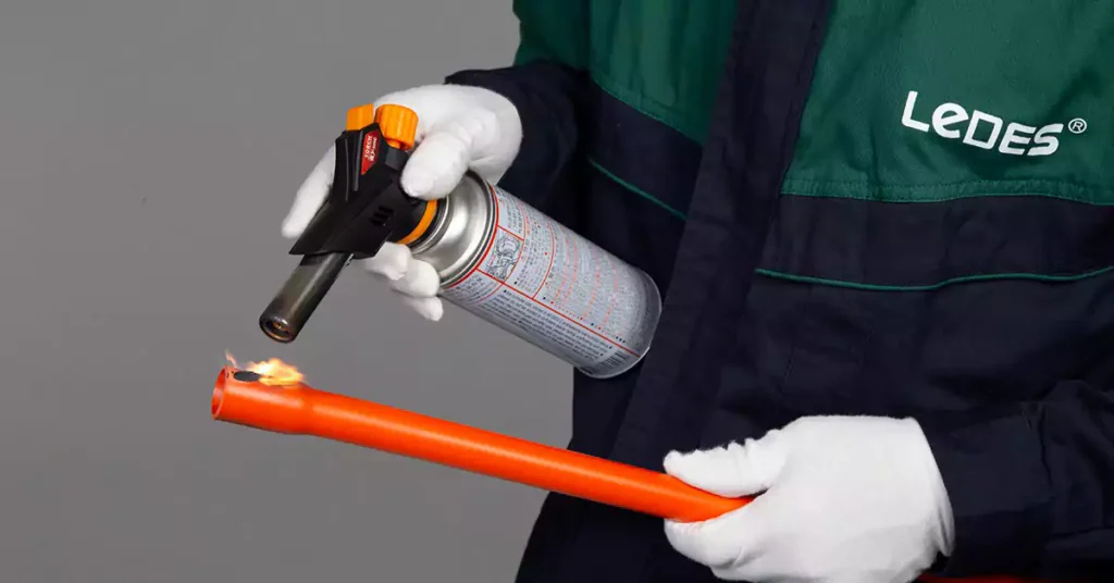
The resistance to burning test ensures that non-metallic and composite conduits and fittings exhibit sufficient resistance to flame propagation. This assessment is crucial for identifying materials that can prevent or limit the spread of fire in electrical installations. Products that pass this test are classified as non-flame propagating, enhancing safety in fire-sensitive environments.
Key Test Overview
This test is conducted using a 1 kW flame in accordance with AS/NZS 4695.2.41 and involves:
- Measuring the ignitability and flame propagation properties of representative samples.
- Evaluating fittings of similar material and design under equivalent conditions.
- Exempting small fittings from testing due to negligible impact on flame behavior.
Apparatus Required
The test setup includes:
- Test Enclosure:
A rectangular metal enclosure with an open face to control environmental variables and minimize draughts.
- Mounting Components:
Metal clamps and steel rods to position conduits and fittings securely.
- Tissue Paper and Pinewood Board:
A layer of white tissue paper (mass of 12–25 g/m²) placed over a pinewood board at the bottom of the enclosure to detect falling molten material.
- 1 kW Burner:
Positioned at a 45 ±2° angle to simulate flame exposure under controlled conditions.
Test Pieces
The test is carried out on three samples:
Kanäle:
A 675 ±10 mm length is mounted vertically using two clamps, spaced 550 ±10 mm apart.
Testing Procedure
The test involves the following steps:
- Montage:
Secure the sample vertically in the enclosure using clamps or suspension.
- Flame Application:
Direct the burner flame at a 45° angle onto the sample for 60 ±1 seconds.
Ensure the flame intersects the surface of the sample at specified points based on the type of test piece.
- Observation:
Monitor flame behavior and any material fallout during the test.
- Post-Test Inspection:
Allow the sample to cool.
Wipe the surface with a water-soaked cloth to remove soot and assess damage.
Akzeptanzkriterien
A sample passes the resistance to burning test if:
- It does not ignite during flame application.
- Burning or charring is absent within 50 mm of the upper and lower clamps after wiping.
- Combustion ceases within 30 seconds after flame removal.
- Tissue paper at the enclosure’s base remains unignited.
- Molten material present on the sample’s surface does not result in burning or charring.
Insulating: The conduit must offer high electrical insulation to protect cables and prevent accidental contact with conductive elements.
Korrosionsbeständigkeit: Materials must resist degradation from moisture, chemicals, and soil.
Ensures the conduit does not interfere with or become affected by electromagnetic fields.
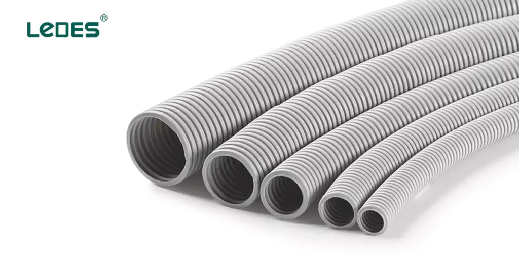
The AS/NZS 2053.5 standard defines the requirements for non-threadable corrugated conduits and their associated fittings made of insulating materials. These conduits are used to protect electrical cables in installations, offering flexibility, mechanical protection, and resistance to external influences. This standard is closely linked to AS/NZS 2053.1, which provides general requirements and guidelines.
This standard applies to:
- Non-threadable corrugated conduits of insulating materials.
- Fittings specifically designed to be used with corrugated conduits.
- Electrical installations requiring cable protection under varying environmental and mechanical conditions.
Corrugated conduits and fittings are classified based on the following, these are what applicable for AS/NZS 2053.5:
According to mechanical properties:
Leichte Beanspruchung
Mittlere Beanspruchung
Schwere Ausführung
According to flame propagation:
Non-flame propagating
Electrical Characteristics:
Ability to provide electrical insulation and prevent continuity issues.
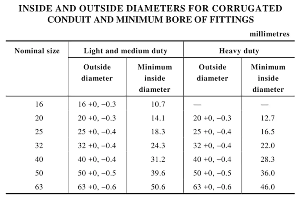
The standard specifies nominal diameters, wall thicknesses, and tolerances for corrugated conduits.
The following mechanical tests ensure corrugated conduit performance under stress:
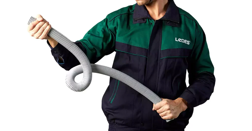
The bending test outlined in AS/NZS 2053.5 ensures that non-threadable corrugated conduits can withstand mechanical stress during installation and use. This test evaluates the conduit’s ability to maintain its structural integrity and functionality when subjected to repetitive bending movements at both standard and low-temperature conditions.
Test Pieces
- Six test pieces are required, each with a length of at least 12 times their outside diameter.
- Three samples are tested at 20°C, while the remaining three are tested at the manufacturer-specified lowest installation temperature.
Test Procedure
- Test at 20°C
(a) Conditioning:
Place the test piece and apparatus in the conditioning chamber for 2 hours at 20°C ±1°C.
(b) Bending Process:
Perform the following sequence by hand:
Bend the test piece 90° to the left.
Return it to the vertical position.
Bend the test piece 90° to the right.
Return it to the vertical position.
Hold the position for 1 minute after each step.
Repeat the sequence 4 times, but on the final cycle, stop at 90° to the right and hold the position for 5 minutes.
(c) Gauge Test:
Rotate the bending apparatus to align the straight sections of the test piece at a 45° angle to the vertical.
Pass the diameter gauge through the conduit under its own weight, ensuring no initial velocity is applied.
- Test at Lowest Installation Temperature
(a) Conditioning:
Place the test piece and apparatus in the conditioning chamber for 2 hours at the manufacturer-specified lowest installation temperature ±2°C.
(b) Repeat Bending Sequence:
Follow the same bending steps and gauge test outlined for 20°C testing.
Criteria for Acceptance
A conduit passes the bending test if:
The gauge passes through the conduit under its own weight without any applied force.
There are no visible cracks on the test piece observed with normal or corrected vision, without magnification.
The Compression Resistance Test as specified in AS/NZS 2053.5 evaluates the ability of corrugated conduits and fittings to resist deformation when subjected to compressive forces. The procedure follows the same methodology outlined for rigid plain conduits in AS/NZS 2053.2, but the acceptance criteria requirement is different.
For corrugated conduits: The difference between the initial outside diameter and the diameter measured under compression does not exceed 25% of the initial diameter.
The collapse test procedure of corrugated conduit is the same as rigid plain conduit, which all test according to AS/NZS 2053.1.
And the corrugated conduit passes the collapse resistance test if:
The specified gauge passes through the minimum internal diameter of the conduit after conditioning, confirming that the internal space remains unobstructed.
The Flexing Test, as outlined in AS/NZS 2053.5, assesses the durability and mechanical resilience of corrugated conduits and their terminating fittings when subjected to repeated bending movements. This test ensures that the conduits can endure dynamic mechanical stresses encountered during installation or in service without compromising their structural integrity or functionality.
Test Procedure
Montage:
Fix the test piece to the oscillating member of the apparatus by its terminating fitting.
Align the conduit so that, at the midpoint of its travel, its axis is vertical and passes through the axis of oscillation.
Flexing Motion:
Subject the test piece to 5000 flexings at a rate of 40 flexings per minute.
Each flexing involves a full cycle of movement, starting from the vertical position and moving backwards and forwards through an angle of 180°.
Inspection:
After completing the test, inspect the test piece for structural damage using normal or corrected vision, without magnification.
Akzeptanzkriterien
There are no visible signs of structural damage upon inspection with normal or corrected vision.
Test Procedure
Heat Conditioning:
Place the test piece and heat test apparatus in the conditioning chamber.
Maintain the specified highest installation temperature for 4 hours.
Lastanwendung:
Apply a load through a 6 mm steel rod, positioned as perpendicular as possible to the conduit’s axis, as shown in bellow.
Load for Resistance to Heat Test of AS/NZS 2053.5
Conduits | Mass kg |
Light | 1.0 |
Medium | 2.0 |
Schwer | 4.0 |
Kühlung:
After 24 hours, remove the test piece and apparatus from the chamber and allow them to cool to room temperature.
Gauge Test:
Remove the load and attempt to pass the appropriate gauge through the test piece under its own weight, without any initial velocity, with the conduit in a vertical position.
Akzeptanzkriterien
The test piece passes if:
The gauge successfully passes through the conduit under its own weight, without any additional force or velocity.
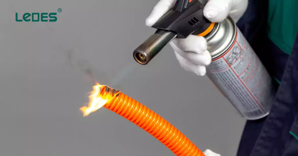
The burning resistance test of corrugated conduits is same as rigid plain conduit. With same requirements.
Electrical Continuity: Not applicable
Insulating: Same requirements as rigid plain conduit in AS/NZS 2053.2.
Same requirements as rigid plain conduit in AS/NZS 2053.2.
Same as rigid plain conduits in AS/NZS 2053.2
AS/NZS 2053.6 specifies the requirements for rigid, non-threadable, profile-wall, smooth-bore conduits and fittings made from insulating materials. These conduits are designed for protecting cables in electrical installations and are available in designated sizes ranging from 90 mm to 150 mm.
Profile-wall, smooth-bore conduits: Conduits with a smooth inner surface for easy cable insertion and a profile wall (which may be hollow) for strength. These conduits are typically not intended for bending.
Light Duty
Mittlere Beanspruchung
Schwerlast
The dimensions of conduits are controlled to ensure compatibility with associated fittings. The specified diameters, socket dimensions and tolerances ensure both mechanical stability and electrical performance.
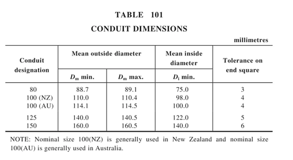
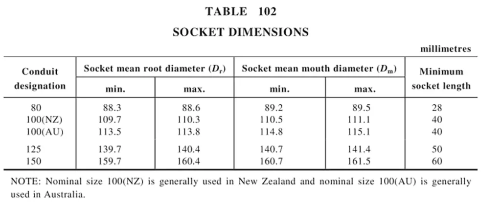
AS/NZS 3053.6 lists the mechanical strength requirements for the Profile-wall, smooth-bore conduits and fittings, details as follows:
The conduits compression test and requirements are similar as rigid plain conduits and corrugated conduits, all tested according to AS/NZS 2053.1. But for profile-wall, smooth-bore conduits, the difference between the initial outside diameter and the diameter measured with the force still applied should not exceed 25%.
The other mechanical strength test for profile-wall, smooth-bore conduits are not applicable, such as: bending, collapse, impact, pull-out strength of joints tests.
The conduits are tested to ensure structural stability at the highest installation temperature specified by the manufacturer. Testing includes exposure to the designated temperature for 4 hours under specified load conditions:
Procedure:
- Place the test piece and apparatus in the conditioning chamber.
- Maintain the chamber at the highest installation temperature (±2°C) for 4 hours.
- Apply the load using a 6 mm steel rod as specified in Table AA1.
- After 24 hours, remove the test piece and allow it to cool to room temperature.
- Test if the gauge passes through the conduit under its own weight.
Acceptance Criterion:
The conduit passes if the gauge moves freely through without resistance.
The materials must exhibit flame retardant properties. Tests ensure that the conduit resists ignition and self-extinguishes after removal of the flame source. Flammability ratings are determined in accordance with AS/NZS 2053.1, same like rigid plain conduits and corrugated conduits.
Electrical Continuity: Not applicable
Insulating: Same as rigid plain conduits and corrugated conduits
Same as rigid plain conduits and corrugated conduits except that, Conduits and fittings of insulating material are classified as having high protection (inside and outside) against corrosive and polluting substances and need not be tested.
Same as rigid plain conduits and corrugated conduits
At Ledes, our commitment to excellence is reflected in every step of the production process for our Australian Standard rigid conduits and corrugated conduits. By aligning with the stringent requirements of standards like AS/NZS 2053.2 and AS/NZS 2053.5, we ensure that our products consistently deliver superior performance, durability, and safety across diverse applications.
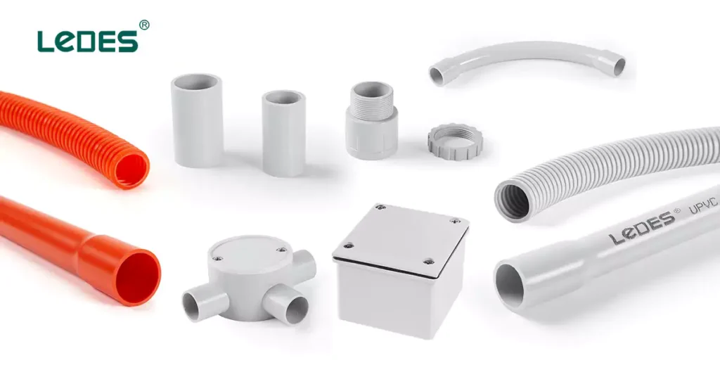
Unser product portfolio includes:
Heavy-Duty Rigid Conduits: Built for high mechanical stress environments, offering superior compression and impact resistance.
Medium-Duty Rigid Conduits: Lightweight yet durable solutions for less demanding applications.
Medium-Duty Communication Rigid Conduits: Lightweight and suitable for communication systems.
Heavy-Duty Corrugated Conduits: Flexible, strong, and capable of withstanding harsh environmental conditions.
Medium-Duty Corrugated Conduits: Ideal for dynamic applications requiring easier handling and installation.
Medium-Duty Communication Corrugated Conduits: For communication applications.
Beschläge: Engineered to ensure secure and reliable connections, including bends, couplings, adaptors, and junction boxes etc.
All Ledes conduits and fittings are manufactured to align with AS/NZS 2053 standards, offering key benefits such as:
Mechanische Festigkeit: Excellent resistance to compression, impact, and deformation under load, ensuring durability in both underground and exposed installations.
Thermal Performance: Stability at high installation temperatures, maintaining structural integrity even under prolonged exposure to heat.
Flammhemmung: Rigid and corrugated conduits meet flame-resistance requirements, with options for Low Smoke Halogen-Free (LSZH) materials that reduce toxic emissions during a fire.
Einfache Installation: Smooth bore for easy cable pulling and profile-wall construction for enhanced strength.
Environmental Resistance: High resistance to UV exposure, moisture, and corrosive substances, making them ideal for outdoor and industrial applications.
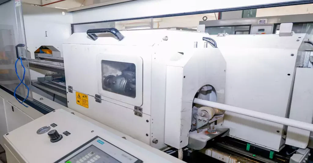
At Ledes, we believe that superior products begin with strict quality control measures at every stage:
- Only premium-grade PVC and insulating materials are used to ensure compliance with mechanical, thermal, and electrical performance standards.
- Raw materials undergo thorough testing for purity, composition, and consistency.
- Low Smoke Halogen-Free (LSZH) Options: To cater to projects with heightened safety demands, such as subway systems, we also offer LSZH conduits and fittings that minimize smoke and toxic gas emissions during fires.
At Ledes, precision manufacturing is the cornerstone of our ability to produce high-performance Australian Standard conduits and fittings. Our state-of-the-art production process ensures each product meets the rigorous demands of AS/NZS 2053 standards. Key highlights of our manufacturing process include:
- Advanced Extrusion Technology
Precision Extrusion:
Using cutting-edge extrusion machines, we produce rigid and corrugated conduits with consistent wall thickness, dimensional accuracy, and a smooth internal bore.
This precision ensures seamless cable pulling and eliminates risks of cable abrasion during installation.
Profile-Wall Construction:
For corrugated conduits, our extrusion process incorporates a reinforced profile-wall structure. This combines flexibility with high mechanical strength, making the conduits suitable for dynamic environments and tight installation spaces.
Controlled Cooling Systems:
After extrusion, conduits pass through controlled cooling tanks to solidify their structure without internal stress, ensuring long-term durability and resistance to environmental factors.
Automated Fitting Production
Injection Molding for Fittings:
Our fittings, including couplings, adaptors, and junction boxes, are manufactured using high-precision injection molding machines.
This process guarantees tight tolerances, smooth edges, and secure fitment, ensuring compatibility with all Ledes conduits and compliance with AS/NZS standards.
- Real-Time Monitoring and Adjustments
Computerized Monitoring Systems:
Throughout the production process, real-time monitoring systems control variables like temperature, pressure, and extrusion speed to ensure uniform quality across all batches.
Any deviations are flagged immediately, and adjustments are made to maintain precision.
Batch Coding and Traceability:
Each batch of product is coded for traceability, enabling thorough quality assurance and ensuring that every product delivered to our clients meets strict specifications.
- Post-Manufacturing Finishing
Cutting and Chamfering:
Conduits are precision-cut to ensure clean ends and uniform lengths, facilitating easier installation. For rigid conduits, chamfering is applied to the ends for a snug fit with fittings.
End-Bell Formation:
For rigid conduits, end-bell formations are produced during the extrusion process to ensure quick and secure connections without additional accessories.
Custom Lengths and Packaging:
We offer customizable lengths and professional packaging to meet project-specific requirements, reducing waste and installation time for contractors.
We select samples from every production batch for testing, replicating the procedures outlined in AS/NZS 2053. These tests include:
Compression resistance
Collapse test
Heat resistance
Flame retardancy
The Melbourne Tunnel Project is a landmark infrastructure initiative aimed at enhancing Melbourne’s urban transit system by delivering a world-class underground rail network. Designed to alleviate congestion and improve connectivity, the project involves constructing twin 9-kilometer tunnels, state-of-the-art stations, and advanced systems to support high-capacity rail services. With stringent safety and environmental standards, the project represents a monumental leap in Australia’s commitment to sustainable and efficient public transport.
Ledes proudly supplied Australian Standard rigid conduits, corrugated conduits, and fittings for the Melbourne Tunnel Project. These components played a pivotal role in ensuring the safety, reliability, and efficiency of the electrical installations within this critical infrastructure.
The key products selected for this project are Ledes’ Low smoke halogen free conduits and fittings, due to excellent fire resistance, low toxicity, and durability, they play a crucial role in the project to ensure meet stringent requirements for electrical safety, reliability, and environmental performance.
The conduits were instrumental in protecting critical cabling systems from mechanical damage, external influences, and fire risks, making them an essential component of this ambitious project.
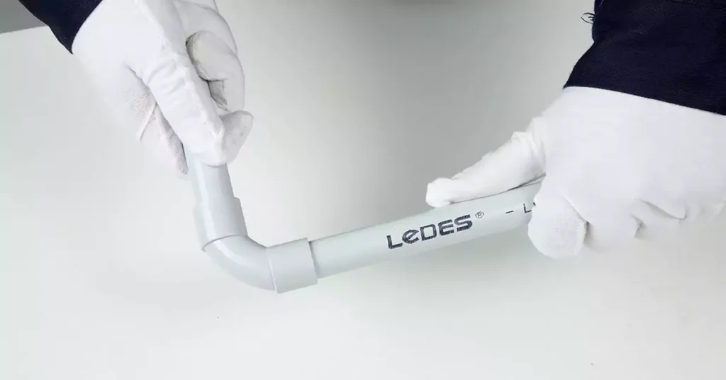
There are 8 pro tips for choosing the right PVC conduit supplier in Australia and New Zealand,
- Compliance with Standards: Ensure the supplier’s products meet Australian Standards (e.g., AS/NZS 2053, IEC 61386) and local building codes.
- Certification and Testing: Verify that the supplier provides certifications and test reports proving compliance with regulatory requirements.
- Proven Project Experience: Look for suppliers with a track record in major local infrastructure projects, demonstrating reliability and adherence to standards.
- Qualitätssicherung: Evaluate their quality control processes, including raw material sourcing, production monitoring, and batch testing for consistent product quality.
- Produktpalette: Choose a supplier with a comprehensive product portfolio, including rigid and corrugated conduits, low-smoke halogen-free options, and various fittings.
- Technische Unterstützung: Consider suppliers that offer technical guidance, installation support, and customized solutions to meet project-specific needs.
- Timely Delivery: Prioritize suppliers with a reliable distribution network and the ability to meet project deadlines.
- Price vs. Value: While price is important, focus on overall value, including product durability, compliance, and reliability. A slightly higher upfront cost may save on replacements and maintenance in the long run.
The AS/NZS 2053 series establishes a comprehensive framework for electrical conduit systems, ensuring safety, performance, and compliance with Australian and New Zealand standards. By understanding the requirements of these standards and choosing products that meet their rigorous criteria, you can achieve reliable and high-quality installations.
At Ledes, we are dedicated to providing Australian Standard conduits and fittings that combine precision manufacturing, stringent quality control, and proven performance. Whether for critical infrastructure projects or everyday applications, our solutions ensure compliance, safety, and durability.
For more information about our products or to discuss your project needs, contact us today.


